-
AeroGCS CONFIG User Manual
8. Hardware Setup
The “Hardware Setup” section of AeroGCS CONFIG allows you to configure the drone’s hardware, including “Airframe” and “Camera” settings.
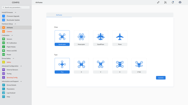
8.1 Airframe
Airframe configuration includes the “Class” and “Type” of the drone.Step 1: To access the Airframe settings, click on “Airframe” under Hardware Setup in the CONFIG section, as shown below:
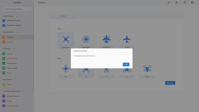
Step 2: If the selected “Class” and “Type” of the drone are correct, click on the “Update” button. This will update the class and type of the drone and display a message saying “Parameters are sent to the device,” as shown below
8.2 Camera
Camera configuration includes “Camera Settings” and “Gimbal Settings.”
8.2.1 Camera Settings:
You can access “Camera Settings” by clicking on the “Camera” option from “Hardware Setup.”
Step 1: Click on the “Camera” option under “Hardware Setup” in AeroGCS CONFIG to open the camera settings screen, as shown below:
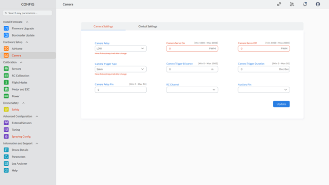
Note: The red highlighting serves as an indicator for both missing parameters and invalid configurations. The default color will be restored once the correct values are entered for these parameters. |
Step 2: On this screen, you can configure and set the required values for the camera, as mentioned in the following sections:
- Camera Relay: Choose “Low” or “High” to control the camera power (similar to a camera switch).
- Camera Servo On/Off: Set PWM (Pulse Width Modulation) values between 1000 and 2000 to control a servo that triggers the camera (higher value = servo moves to activate camera).
- Camera Trigger Type: Choose “Servo” (uses a servo) or “Relay” (uses an electronic switch) to trigger the camera automatically.
- Camera Trigger Distance (m): Set the distance at which the camera triggers automatically (0-1000 meters).
- Camera Trigger Duration (ds): Set the duration (in deciseconds) for which the camera captures images when triggered automatically (0-50 deciseconds).
- Camera Relay Pin: Assign a PIN (0-50) on your drone’s flight controller to control the camera relay.
- RC Channel: Select the RC (Remote Control) channel that controls camera functions through your transmitter (refer to your drone’s manual).
- Auxiliary Pin: Assign a PIN (on your drone’s flight controller) for additional camera functions (consult your drone’s manual for specific functionalities linked to auxiliary pins).
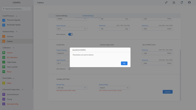
Step 3: – After configuring the parameters, click “Update” to send them to the device. If any parameter is missing or has an incorrect value, an error message will be displayed, and the field containing the incorrect value will be highlighted in red. Otherwise, a message saying “Parameters are sent to the device” will be shown.
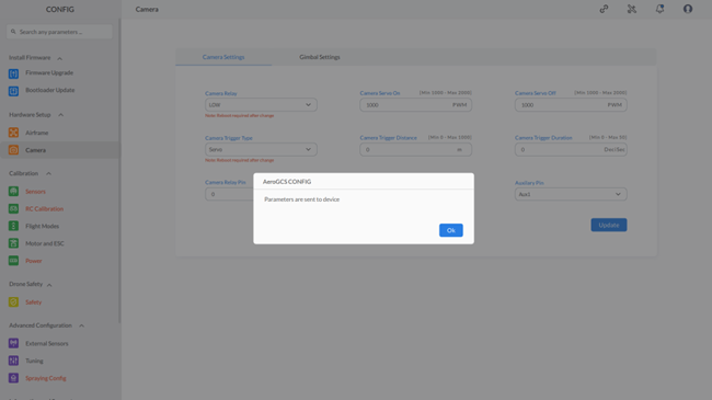
Step 4: Click on “OK” to close the message.
Additional Notes:
|
8.2.2 Gimbal Settings
You can access “Gimbal Settings” by clicking on the “Camera” option from “Hardware Setup.”
Step 1: To access gimbal settings, select “Camera” and switch to the gimbal settings screen, as shown:
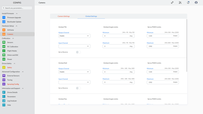
Note: The red highlighting serves as an indicator for both missing parameters and invalid configurations. The default color will be restored once the correct values are entered for these parameters. |
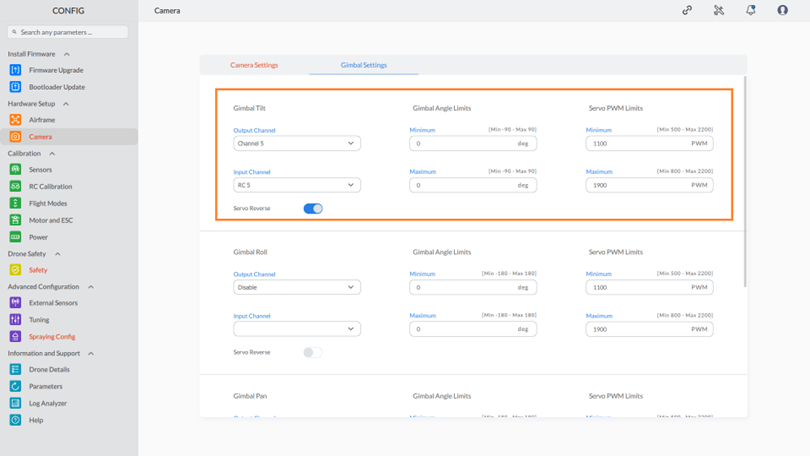
Step 2: Configuring Gimbal Tilt Settings:
- Output Channel Configuration: Select the desired channel from the drop-down list.
- Input Channel Configuration:
- Choose a channel from the output channel drop-down list to enable input channel customization.
- From the input channel drop-down list, select the appropriate input channel.
- Choose a channel from the output channel drop-down list to enable input channel customization.
- Gimbal Angle Limits: Set the limits for the gimbal angle to ensure clear images. Adjust these limits as needed.
- Servo PWM Limits: Specify the servo PWM limits, ensuring they stay within the range of 500 to 2200. Avoid exceeding these limits on either side.
- Servo Reverse Toggle: Use the toggle button to enable or disable the “Servo reverse” setting as needed.
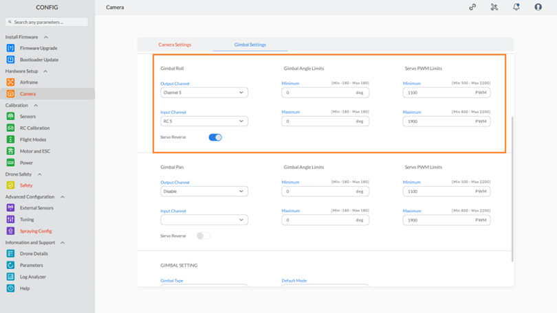
Step 3: Configuring Gimbal Roll Settings:
- Output Channel Configuration: Select the desired channel from the drop-down list.
- Input Channel Configuration:
- Choose a channel from the output channel drop-down list to enable input channel customization.
- From the input channel drop-down list, select the appropriate input channel.
- Choose a channel from the output channel drop-down list to enable input channel customization.
- Gimbal Angle Limits: Set the limits for the gimbal angle to ensure clear images. Adjust these limits as needed.
- Servo PWM Limits: Specify the servo PWM limits, ensuring they stay within the range of 500 to 2200. Avoid exceeding these limits on either side.
- Servo Reverse Toggle: Use the toggle button to enable or disable the “Servo reverse” setting as needed.
Step 4: Configuring Gimbal Pan Settings:
- Output Channel Configuration: Select the desired channel from the drop-down list.
- Input Channel Configuration:
- Choose a channel from the output channel drop-down list to enable input channel customization.
- From the input channel drop-down list, select the appropriate input channel.
- Choose a channel from the output channel drop-down list to enable input channel customization.
- Gimbal Angle Limits: Set the limits for the gimbal angle to ensure clear images. Adjust these limits as needed.
- Servo PWM Limits: Specify the servo PWM limits, ensuring they stay within the range of 500 to 2200. Avoid exceeding these limits on either side.
- Servo Reverse Toggle: Use the toggle button to enable or disable the “Servo reverse” setting as needed.
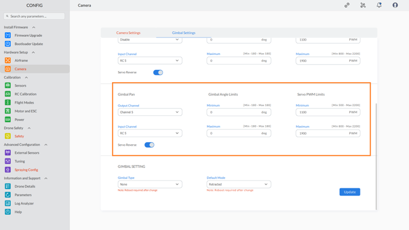
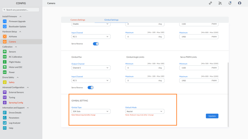
Step 5: Configuring Gimbal Settings:
To configure gimbal settings, follow these steps:
- Gimbal Type: Choose the type of gimbal from the provided dropdown list.
- Default Mode: Pick the default operational mode for the gimbal using the dropdown list.
Step 7: Click on “OK” to close the message.
This completes the camera setting process.
Additional Notes:
|