-
AeroGCS CONFIG User Manual
12. Flyview for Manual Flight Testing
The Flyview feature in AeroGCS CONFIG allows users to perform manual flight testing with a clear, real-time visual interface. This feature is crucial for monitoring the drone’s performance and ensuring safe and accurate flight operations. Below is a detailed description of the Flyview interface and its components:
12.1 Accessing Flyview
To access Flyview for manual flight testing, navigate to the main screen of AeroGCS CONFIG and click the Flyview button. The interface will display a real-time satellite map of the drone’s location and additional flight data.
12.2 Flyview Interface Components
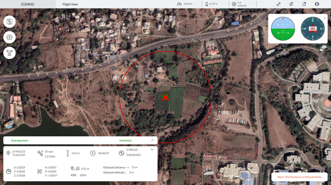
- Real-Time Satellite Map:
- The main section of the Flyview screen displays a real-time satellite map with the drone’s current location marked by a green arrow.
- A red circle indicates the drone’s geofence boundary, providing a clear visual representation of the operational area.
- Flight Data Overlay:
- At the top of the screen, several key metrics are displayed:
- Speed: The current speed of the drone (e.g., 0.02 m/s).
- Voltage: The current voltage of the drone’s battery (e.g., 12.59 V).
- Current: The current being drawn by the drone (e.g., 0 A).
- The right-hand corner features an artificial horizon and compass for additional orientation.
- At the top of the screen, several key metrics are displayed:
- Flight Status Information:
- The bottom of the screen shows comprehensive flight status information, including:
- GPS Coordinates: The current GPS coordinates (latitude and longitude).
- Satellites: Number of GPS satellites connected and HDOP value.
- Altitude: The drone’s altitude from the take-off point.
- Flight Mode: See your current flight mode, such as “Stabilize,” displayed here. Click the arrow on the right to select different modes.
- Arm Status: Indicates whether the drone is armed or disarmed.
- Obstacle Distance and Altitude: Readings from the obstacle avoidance sensors.
- RSSI: Signal strength indicator.
- Distance from Home: The drone’s distance from the home point.
- Flight Time: Total duration of the current flight.
- The bottom of the screen shows comprehensive flight status information, including:
12.3 Manual Flight Controls:
- The left-hand side of the screen contains buttons for basic manual control functions:
- Arm: Prepares the drone’s motors for flight.
- Disarm: Stops the drone’s motors for safety.
- Camera Trigger: Activates the camera to capture images or videos.
- The left-hand side of the screen contains buttons for basic manual control functions:
12.4 Return to AeroGCS CONFIG Settings
To return to AeroGCS CONFIG settings from Fly View, click on the “Settings ” button.
12.5 Using Flyview for Manual Flight Testing
- Preparing for Manual Flight:
- Ensure that the drone’s propellers are properly attached and the battery is fully charged.
- Verify that the GPS signal is strong and the number of satellites is sufficient for stable flight.
- Initiating Manual Flight:
- Use the on-screen controls to arm the drone and select the desired flight mode.
- Take off by clicking the take-off button or using manual controls on the remote controller.
- Monitoring Flight:
- Keep an eye on the real-time satellite map and the drone’s position within the geofence boundary.
- Continuously monitor flight data and status indicators for any anomalies or warnings.
- Ending Manual Flight:
- Safely land the drone using the landing button or manual controls.
- Disarm the drone once it has landed to ensure safety.
- Post-Flight Analysis:
- Review the recorded flight data and logs for performance analysis and troubleshooting.
Flyview is an essential tool for drone operators, providing a comprehensive and intuitive interface for manual flight testing. It enhances situational awareness, ensures flight safety, and facilitates efficient flight operations.
- Review the recorded flight data and logs for performance analysis and troubleshooting.
Table of Contents