-
AeroGCS DEFENCE
5. System Tools and Settings
This chapter provides comprehensive guidance on system-level functionalities and configuration tools available in AeroGCS DEFENCE. These tools enable operators to manage drone connections, configure application behavior, adjust settings, access logs, and customize flight metrics.
The features covered in this chapter ensure that the application remains adaptable to varied operational needs—whether in defence, surveillance, or inspection scenarios. Each utility or setting described herein contributes to improving control, situational awareness, and mission precision.
Key Sections Covered:
- Connecting to Drone: Establishing and managing communication with supported drones via multiple interface types.
- Live Camera Feed and Settings: Accessing and managing video streams and camera configurations.
- Map Manager: Configuring map layers and caching offline map data.
- User Management: Adding, editing, or deleting users and assigning roles.
- Application and General Settings: Adjusting unit preferences and system behavior.
- RPA Settings: Custom parameters for the connected Remotely Piloted Aircraft (RPA), enhancing mission performance.
✅ This chapter applies to both novice users requiring initial setup guidance and experienced operators who need to fine-tune mission environments or drone behavior.
⚠️ Important Note on Reboot Requirement Some settings in the System Tools and Settings module require the drone to be rebooted for the changes to take effect. Wherever applicable, a “Reboot Required” message is explicitly shown near the corresponding setting in the AeroGCS DEFENCE interface. Please ensure you reboot the drone after modifying such settings to ensure correct system behavior and mission safety. |
5.1. Connecting to Drone
Establishing a reliable connection between the AeroGCS DEFENCE software and the drone is a critical prerequisite for mission planning and execution. AeroGCS DEFENCE supports multiple communication protocols for flexible drone connectivity, including Serial, TCP, UDP, and Bluetooth. Once a drone is connected, all flight control and mission planning functions become active.
| ⚠️ Note: Ensure the drone is powered on and within communication range before attempting to connect. |
Accessing the Drone Connection Interface
Follow the steps below to access the drone connection window:
Steps:
- Click the three-dot menu (⋮) on the top-right corner of the Home screen.
- From the dropdown, select the Connect Or simply click on from top navigation bar.
- A Connection window appears, allowing the user to select and configure the connection method.

Supported Connection Types in AeroGCS DEFENCE
| Protocol | Description |
| Serial | Wired USB-based communication, commonly used for stable connections. |
| TCP | Used for connecting over LAN or Wi-Fi using IP addresses and port numbers. |
| UDP | A lightweight, low-latency alternative to TCP for certain network setups. |
| Bluetooth | Wireless short-range option for basic connectivity. |
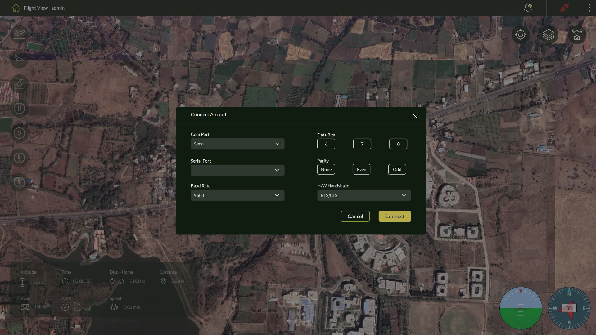
5.1.1 – Using Serial Port
This is the most used method for stable, direct connections.
Steps:
- From the dropdown, select Serial.
- Configure the parameters below:
- Serial Port: Select the appropriate COM port.
- Baud Rate: Choose the correct baud rate (e.g., 57600 or 115200).
- Data Bits: Typically 8.
- Parity: Choose None/Even/Odd as per requirement.
- Flow Control: Choose between RTS/CTS or XON/XOFF.
- Click Connect to initiate communication.
5.1.2 – Using TCP
For wireless or network-based connectivity.
Steps:
- Select TCP as the connection type.
- Enter the following:
- Host Address (e.g., 0.0.1 for localhost)
- Listening Port
- Click Connect to establish the link.

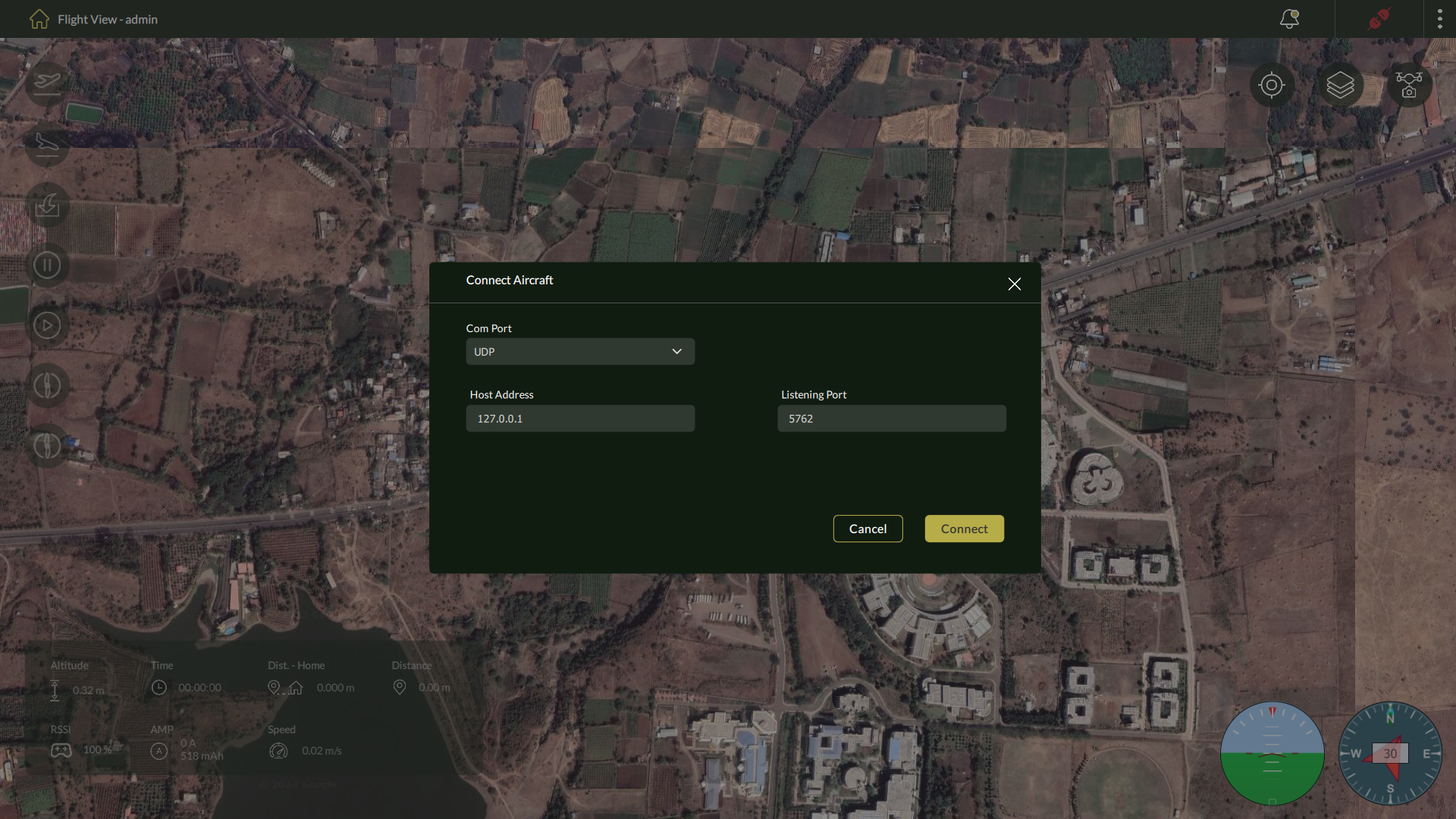
5.1.3 – Using UDP
UDP is suitable for scenarios where low-latency communication is required, though it is less reliable than TCP.
Steps:
- Select UDP from the connection type dropdown.
- Input:
- IP Address
- Port Number
- Click Connect.
5.1.4 – Using Bluetooth
For nearby wireless connections using Bluetooth.
Steps:
- Select Bluetooth from the connection dropdown.
- Click Scan to discover available devices.

3. Select the appropriate drone device from the list.
4. Click Connect to pair and establish communication.
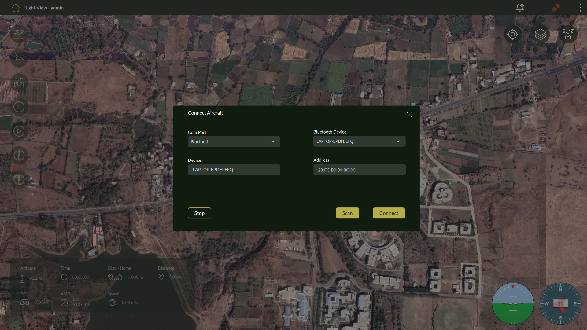
| Note: You may be prompted to enable permissions for Bluetooth scanning. |
✅ Upon successful connection, a notification “Communication Link Established” will appear, and the pin at top navigation bar will turn green
5.2 Live Camera Feed and Settings
Overview
The Live Camera Feed feature in AeroGCS DEFENCE provides real-time visual feedback from the drone’s onboard camera. This functionality is essential for reconnaissance, surveillance, and visual monitoring tasks during flight operations.
The camera interface includes tools for video streaming, image capture, and gimbal adjustment. It is accessible from the Flight View screen via the Camera icon located at the top-right toolbar.
Accessing the Live Camera Panel
Steps to View Camera Feed:
- Ensure drone is connected (refer to the pin icon in the top bar to verify connection).
- Go to the Flight View
- Click on the Camera icon (📷) in the top-right corner.
- The Live Camera Panel opens on the right side of the screen.
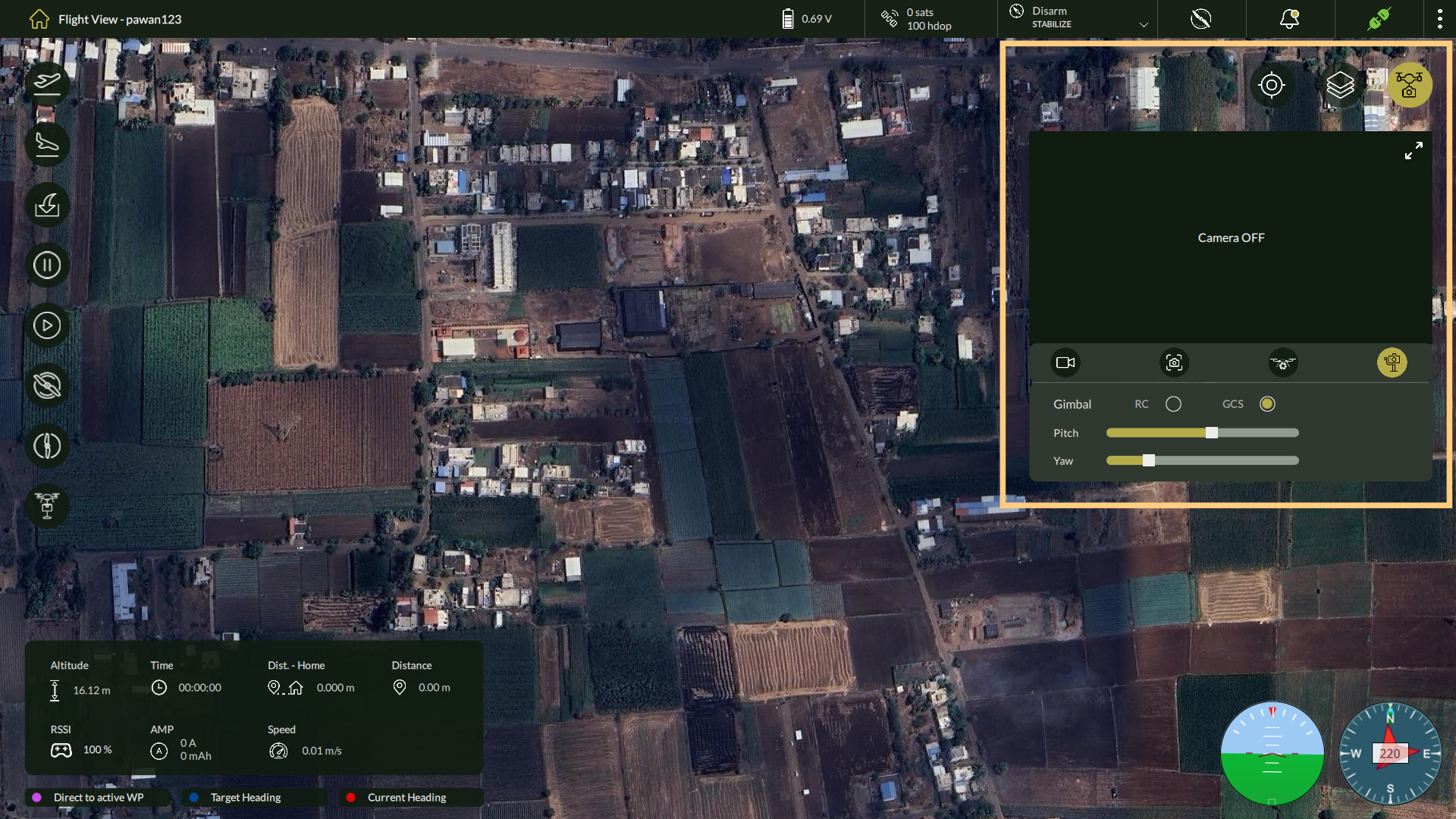
| Note: If the camera feed is inactive or not connected, the message “Camera OFF” will appear in the video panel. |
Camera Control Panel Features
| Control | Description |
| Live Video Preview | Displays the current video feed from the drone. |
| Capture | Takes a still photo and saves it to the local system. |
| Record | Starts or stops video recording. A time counter will indicate recording progress. |
| Camera Trigger | Sends a hardware-level command to trigger the onboard camera directly (for drones equipped with trigger-compatible cameras). |
| Gimbal Control | Allows control of the camera’s pan and tilt using either: • RC Mode – Follow remote control inputs • GCS Mode – Use sliders to adjust from the Ground Control Station |
Gimbal Adjustment Options:
| Parameter | Description |
| Pitch | Adjusts the camera angle vertically (up/down) |
| Yaw | Adjusts the camera angle horizontally (left/right) |
| RC/GCS Toggle | Choose control mode: RC (manual stick) or GCS (via sliders) |
Tips
|
Accessing Media Files
- All captured media (images and videos) are stored in the system-defined Media folder.
- These files can be viewed, shared, or processed later for analysis or reporting.
Object Tracking in Live Camera Feed
Enabling Object Tracking
Object Tracking is available only when the Live Camera Feed is active.
Steps to Start Object Tracking:
- Connect to the Drone Establish a connection using one of the supported methods described in Section 5.1.
- Open the Live Camera Panel From the Flight View, click the Camera icon (📷) in the top-right toolbar. Verify that the live video feed is displayed.
- Draw the Tracking Shape
In the live feed window:
- Position the cursor at one corner of the object to be tracked.
- Click and hold, then drag to draw a bounding box around the object.
- Release the mouse button to confirm the selection.
- Begin Tracking
Once the selection is released, AeroGCS DEFENCE automatically locks onto the annotated object and begins tracking it in real time.
- The system continuously adjusts pan and tilt to maintain the object in the center of the frame.
- Predictive motion algorithms are applied if the object temporarily exits the visible frame.
- Tracking remains active until:
- The operator manually cancels it, or
- The live feed is closed.
To stop tracking:
- Right-click anywhere in the live feed and select Stop Tracking, or
- Close the Live Camera Panel.
Best Practices for Reliable Tracking
| Recommendation | Benefit |
| Select objects with high visual contrast from the background | Improves lock stability |
| Avoid abrupt drone maneuvers while tracking | Reduces tracking loss |
| Track single, distinct targets | Prevents confusion with similar objects in frame |
| Use optimal lighting conditions | Enhances visual clarity for the tracking algorithm |
5.3 Map Manager
Overview
The Map Manager in AeroGCS DEFENCE provides users with a centralized module to manage various types of geospatial maps—Raster, Vector, and Offline—which are essential for mission planning, field analysis, and operational visualization. This tool supports uploading and organizing georeferenced map layers, giving users enhanced control in both connected and disconnected environments.
Accessible from the three-dot menu on the top-right corner of the Flight View screen, the Map Manager is a critical utility for configuring and maintaining map layers used across mission planning workflows.
Understanding Map Types in AeroGCS DEFENCE
| Map Type | Description |
| Raster Maps | Raster maps are pixel-based (image) data formats, such as .tif or .tiff, used for satellite imagery or orthophotos. Each pixel contains specific location and visual data. These are ideal for drone survey maps or orthomosaic overlays. |
| Vector Maps | Vector maps consist of point, line, and polygon data layers representing features like roads, boundaries, and waypoints. These are lightweight and scalable, often used for navigation overlays and boundary definitions. |
| Offline Maps | Offline maps allow users to operate in areas with no internet access by storing tiles of selected map areas. These are downloaded from online sources (like Google Maps or OSM) for future use. |
Operational Overlays and Airspace Constraints
| Overlay Type | Description |
| No Fly Zones | Geospatial zones where UAVs are restricted from entering. Defined by administrators using circular or polygonal boundaries with designated zone types (Red – Strictly restricted, Yellow – Caution). These overlays help enforce airspace compliance and mission safety. |
Accessing the Map Manager
Steps to Access:
- Navigate to the Flight View.
- Click the three-dot menu at the top-right.
- Select Map Manager from the dropdown list.
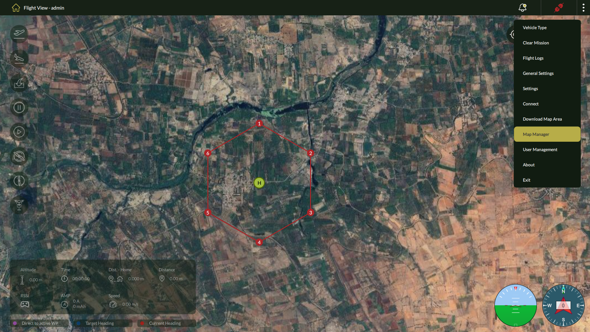
The interface displays four tabs:
- Raster Maps
- Vector Maps
- Offline Maps
- NoFly Zone List
Each tab provides access to corresponding map management tools.
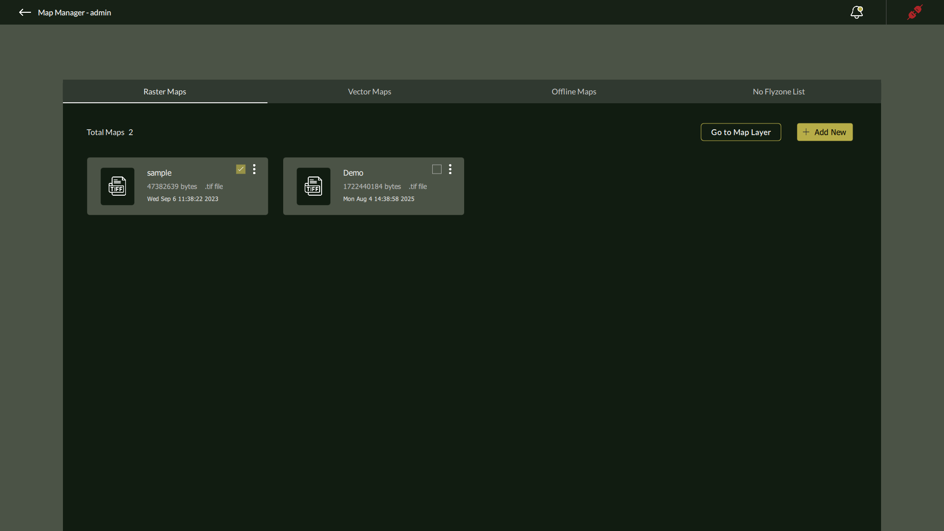
Raster and Vector Maps
The Raster Maps and Vector Maps tabs list all uploaded map files with the following metadata:
- File Name
- Size in bytes
- File Type (e.g., .tif)
- Upload Date & Time
Actions Available:
- ⋮ Three-dot menu for future contextual actions (delete – Currently available).
- Go to Map Layer – instantly navigates the Fly View to the selected map’s geolocation.
Use Case Example: Upload orthophotos post-flight from drone surveys in .tif format under Raster Maps, and vector boundaries or flight corridors under Vector Maps.
Adding Raster or Vector Maps
Steps to Add a Map:
- Select the Raster Maps or Vector Maps
- Click on + Add New .
- A file browser opens; select your georeferenced .tif or vector-compatible file.
- Upon upload, it will appear in the list with its metadata.
| 🛈 Files must be correctly geotagged for proper alignment in the Fly View. |
Offline Maps
The Offline Maps tab in the Map Manager allows users to pre-download map tiles and store them locally for use in remote environments where internet connectivity may be unavailable or unreliable. This ensures uninterrupted access to geospatial data during flight operations.
Offline maps are particularly useful for:
- Field deployments in remote or high-security zones.
- Pre-mission planning in areas with no internet coverage.
- Reducing network dependency during flight control or mission execution.
Adding an Offline Map Area
Follow these steps to add a new offline tile set:
- Open Map Manager
- Click the three-dot menu on the top-right of the Flight View screen.
- Select Map Manager from the dropdown.
- Access Offline Maps Tab
- Navigate to the Offline tab within the Map Manager interface.
- Navigate to the Offline tab within the Map Manager interface.
- Initiate Map Download
- Click the + Add New button.
- The Add New Offline Area panel will appear.
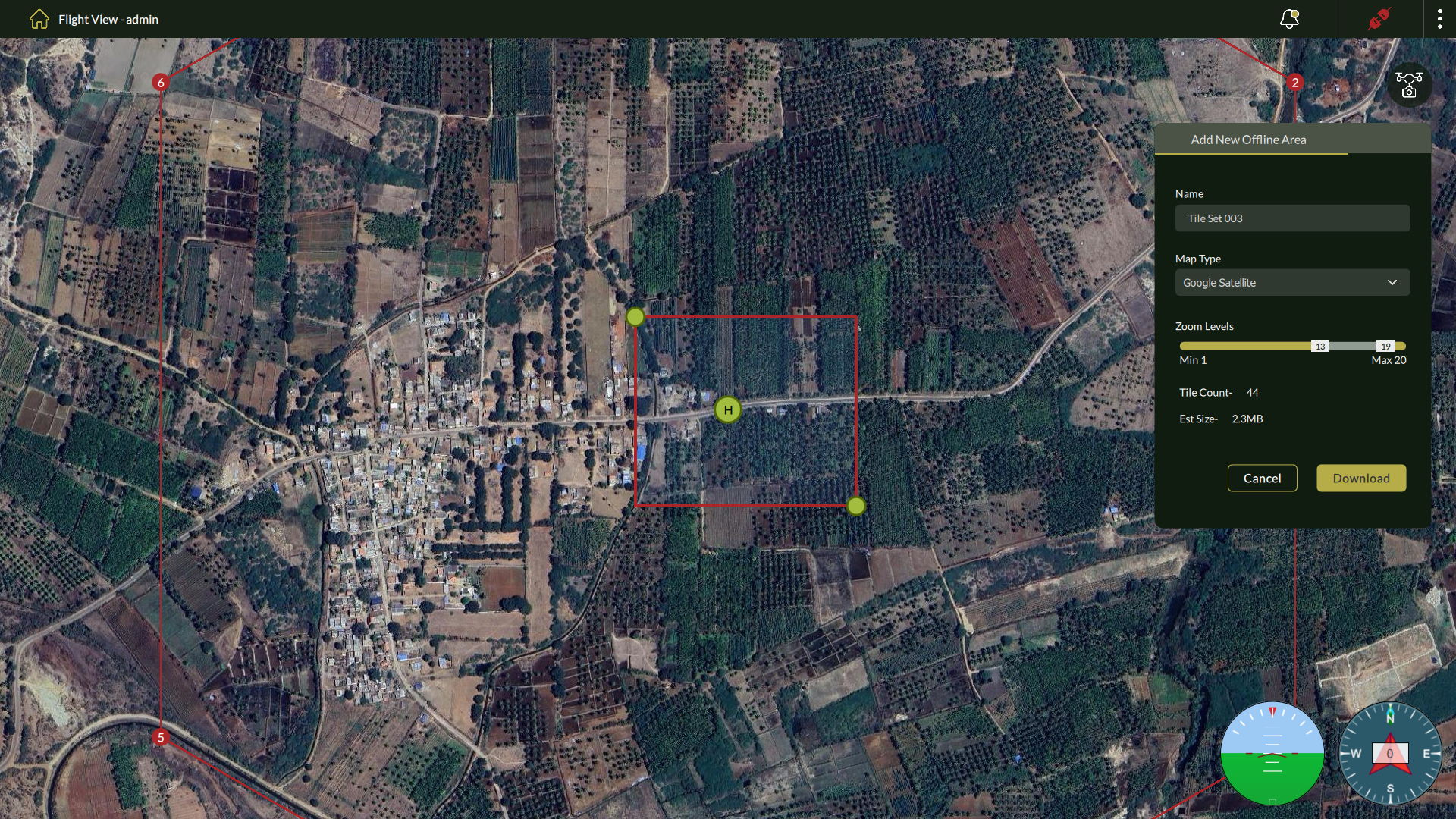
4. Configure Offline Area Settings
Fill in the following fields:
| Field | Description |
| Name | Enter a unique name for the tile set (e.g., Tile Set 003). |
| Map Type | Select the base map source (e.g., Google Satellite). |
| Zoom Levels | Adjust the zoom level range using the slider. Lower zooms cover wider areas; higher zooms show finer detail but increase download size. |
| Tile Count | Displays the number of tiles selected. |
| Est. Size | Estimated file size of the map tiles based on the selected area and zoom. |
5. Define Area of Interest
- Use the resizable red bounding box on the map to select the area to download.
- Drag the corners to adjust coverage as needed.
6. Download or Cancel
- Click Download to start downloading the selected offline map tiles.
- Click Cancel to discard the operation.
Once downloaded, the tile set becomes available within the Offline tab and will be accessible in both planning and live operational modes—even without internet access.
Viewing and Managing Offline Map Tiles
Once a tile set has been downloaded, it can be easily viewed, renamed, or deleted directly from the Offline tab within the Map Manager.
Viewing an Offline Map Tile
- Go to the Map Manager from the Flight View (three-dot menu).
- Select the Offline
- Click on the desired offline map tile entry from the list.
This opens the Offline Map Tile View where the tile’s defined area is displayed on the map.
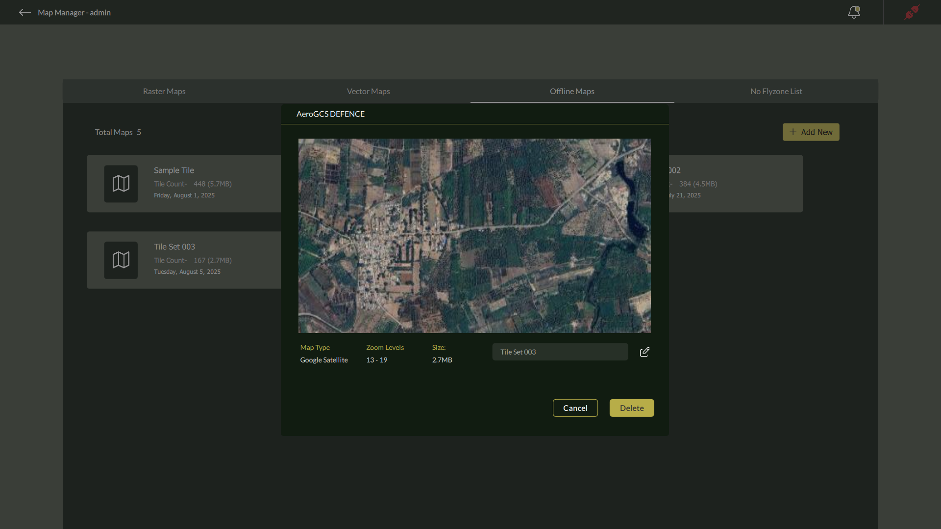
Renaming an Offline Map Tile
- Click on the Edit icon (🖉) next to the offline map tile name.
- A Rename Tile dialog appears, prompting you to enter a new name.
- Enter the desired name and click OK to confirm.
This is useful for organizing map tiles by region, mission, or operational priority.
Deleting an Offline Map Tile
- While viewing the offline tile, click the Delete button available in the tile interface.
- A confirmation dialog will appear with the message:
“Do you want to delete <offline map name> and all its tiles?”
- Click Yes to permanently remove the tile and all associated data, or No to cancel the operation.
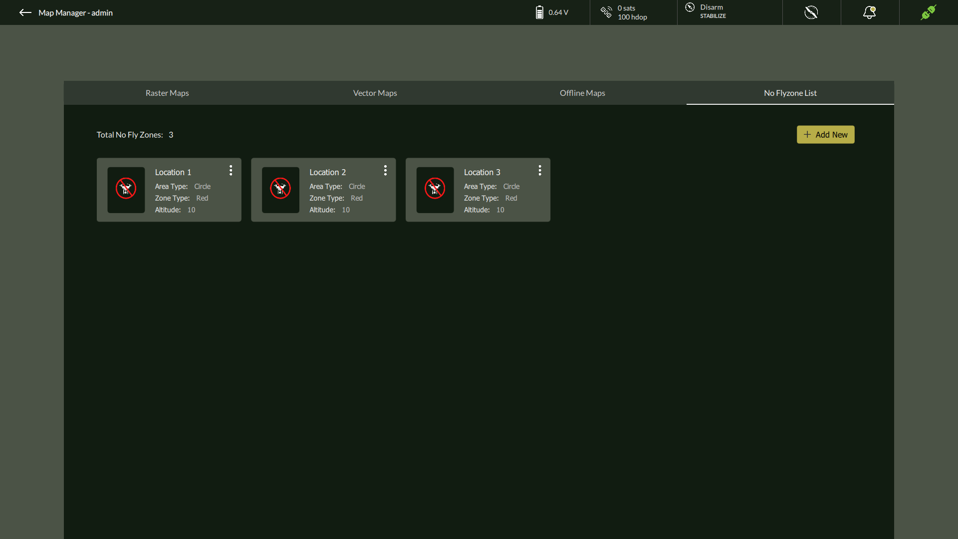
No Fly Zone List
The No Fly Zone List is the fourth tab in the Map Manager and provides a critical tool for defining and managing airspace restrictions to enhance mission safety and ensure regulatory compliance. Operators can add predefined No Fly Zones—both permanent and mission-specific—to prevent UAVs from entering restricted or hazardous regions.
These zones can be configured using either Circle or Polygon area types, and are categorized as either Red (Restricted) or Yellow (Caution) zones based on severity. All configured zones are displayed in a list format within this tab for easy management.
Important:
|
Adding a No Fly Zone
To define a new No Fly Zone:
- Open the Map Manager from the three-dot menu in the Flight View.
- Click on the No Fly Zone List
- Click the ➕ Add New button located at the top-right of the tab.
- The Add New No Fly Zone window will appear.
- Select the Area Type as either Circle or Polygon.
- Configure the zone using the parameters described below.
1. Adding a Circular No Fly Zone
When Circle is selected as the area type:
- Zone Type: Select either Red or Yellow.
- Maximum Altitude: Enter the vertical limit of the zone in centimeters.
- Radius: Enter the radius in kilometers to define the coverage area.
- Latitude & Longitude: Provide coordinates for the center point of the circle.
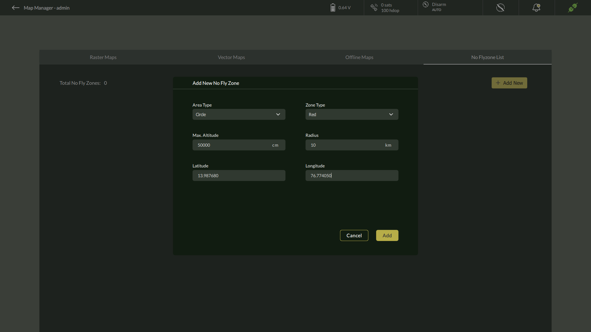
After reviewing the inputs:
- Click Add to create the zone.
- Click Cancel to abort the operation.
2. Adding a Polygon No Fly Zone
When Polygon is selected:
- Zone Type: Select either Red or Yellow.
- Maximum Altitude: Enter the zone’s height limit in centimeters.
- Number of Points: Define the number of polygon vertices.
- The interface will dynamically display input fields for each point.
- Latitude & Longitude: Enter precise coordinates for each vertex of the polygon.
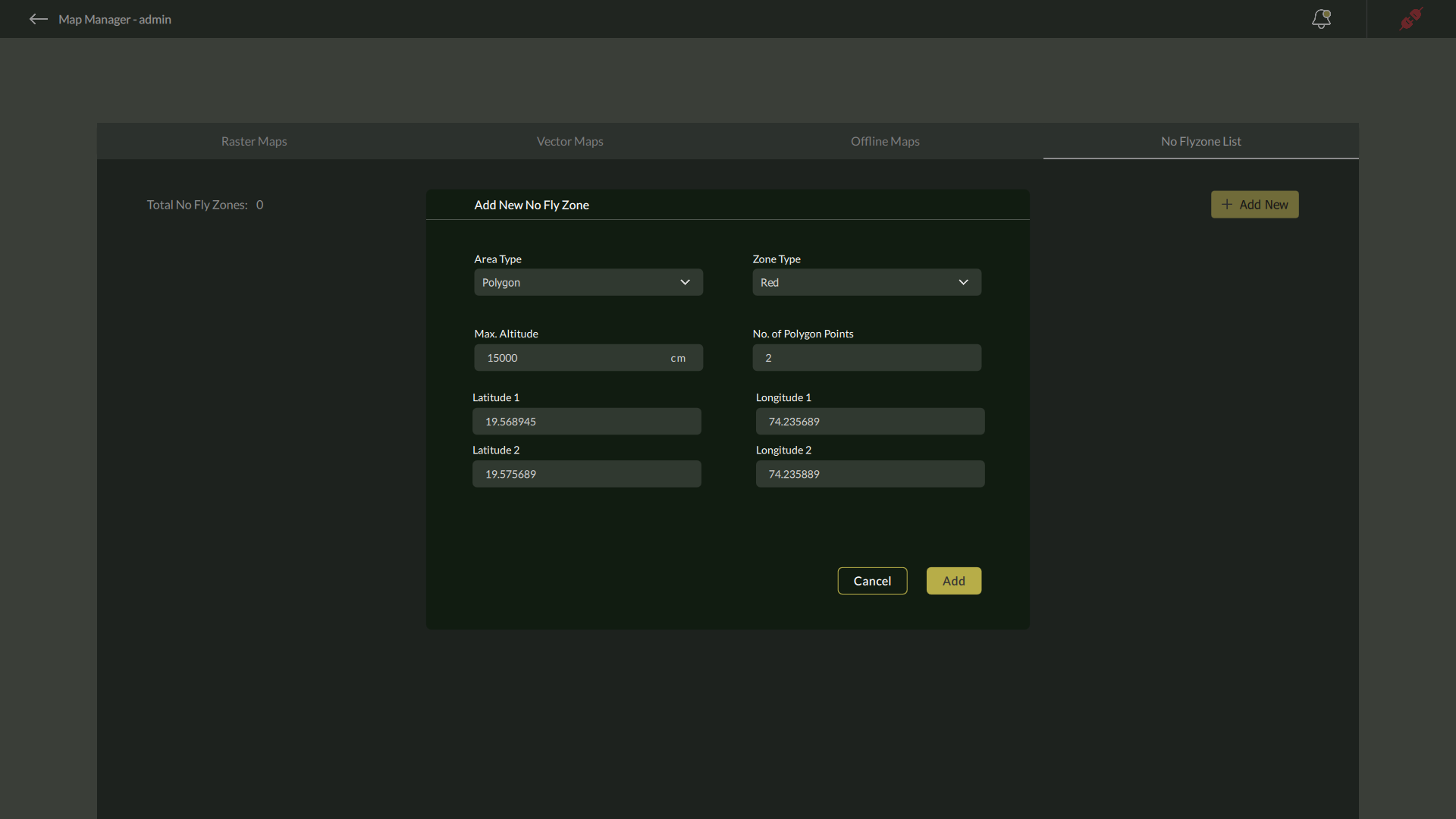
Once all details are entered:
- Click Add to save the zone.
- Click Cancel to exit without saving.
Managing No Fly Zones
After creation, all defined zones appear as cards within the No Fly Zone List tab. Each card includes zone details and a three-dot menu (⋮) for zone-specific actions.
- Deleting a Zone:
- Click the three-dot menu (⋮) on the desired zone card.
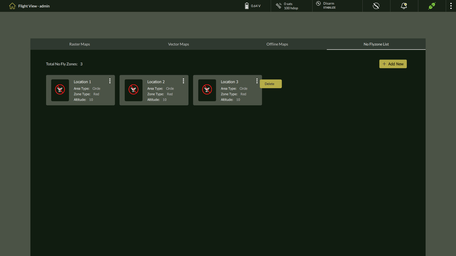
- Select Delete from the dropdown.
- A confirmation dialog will appear:
“Do you want to delete <zone name> and all its tiles?” - Click Yes to confirm and permanently remove the zone.
Best Practices
- Use Red Zones for strictly restricted areas (e.g., military bases, sensitive infrastructure).
- Use Yellow Zones to mark cautionary airspace (e.g., near populated zones).
- Always verify coordinate values to ensure zone accuracy.
- Plan and add No Fly Zones before executing mission routes.
5.4. User Management
AeroGCS DEFENCE provides a built-in User Management module to securely manage operator access and control permissions. This ensures that only authorized personnel can operate drones, access mission-critical data, or modify system settings.
Only ADMIN user has access to the User Management feature.
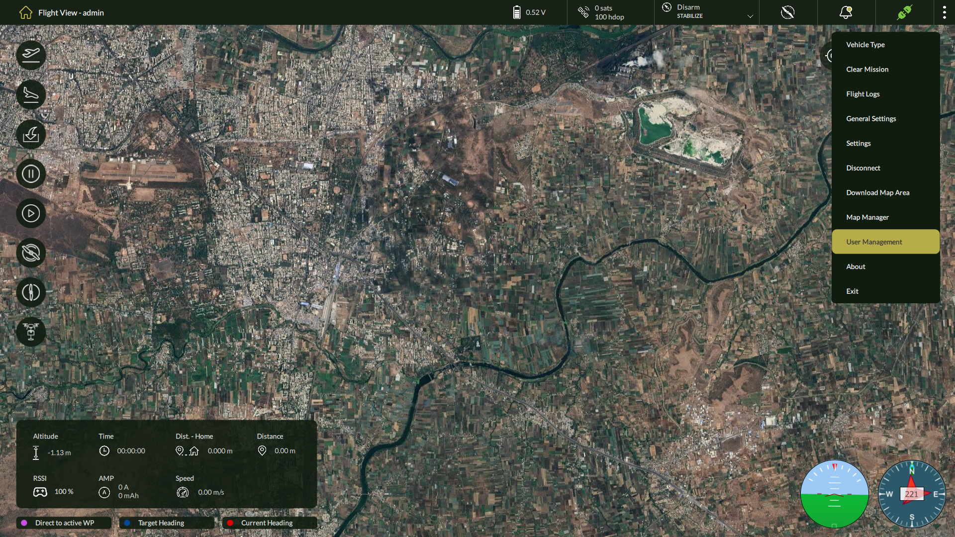
Accessing User Management
To open the User Management panel:
- On the Flight View screen, click the three-dot menu in the top-right corner.
- Select User Management from the dropdown list.
User Roles
| Role | Description |
| ADMIN | Full privileges: can manage users, view logs, and access all system settings. |
| USER | Operational access: limited to flying drones and mission activities only. |
Steps to Add a New User
1. Click Add User
– Click the + (Add User) button.
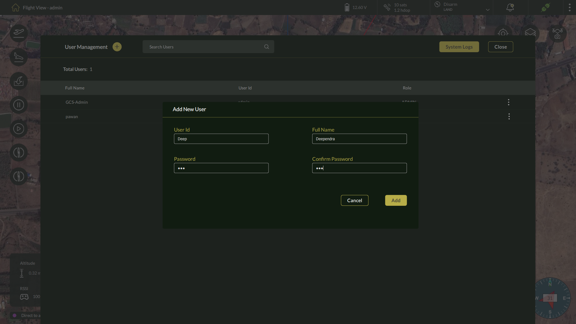
2. Enter Required User Details
– Fill in the following fields:
| Field | Description | Required |
| Full Name | Enter the user’s full name | ✔️ |
| Username | Define a unique login ID | ✔️ |
| Password | Create a secure password | ✔️ |
| Confirm Password | Re-enter the password | ✔️ |
3. Save the User
– Click Save to complete user creation.
– A confirmation message will appear upon success.
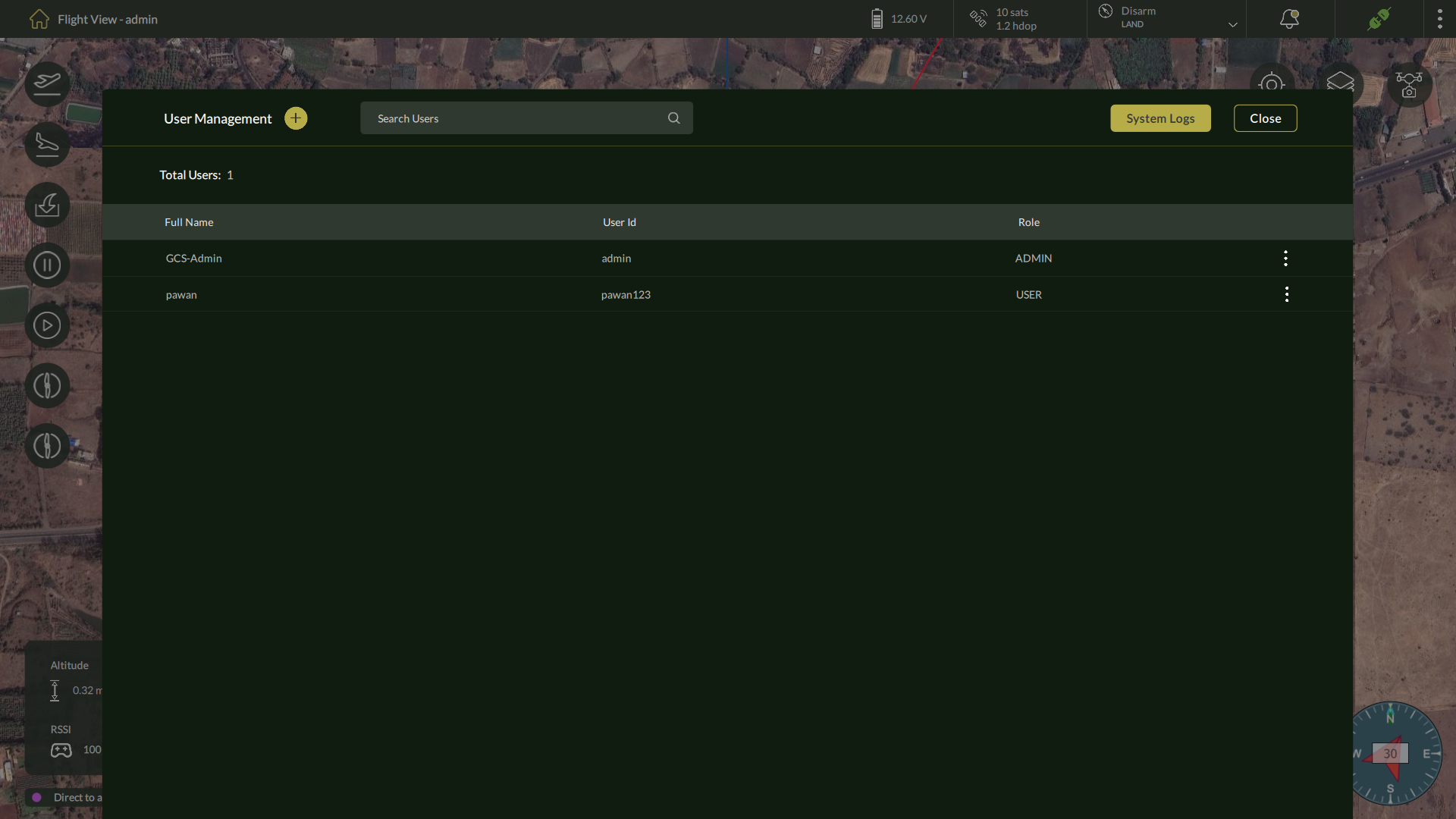
4. User Ready for Login
– The newly created user appears in the User Management table.
– They can now log in via the main login screen using their credentials.
Edit or Delete Users
Each user row includes a three-dot menu on the right.
- Edit User – Modify full name or role.
- Delete User – Remove a user account permanently.
⚠️ Note: ADMIN users cannot be deleted for security reasons. |
Search Users
Viewing System Logs
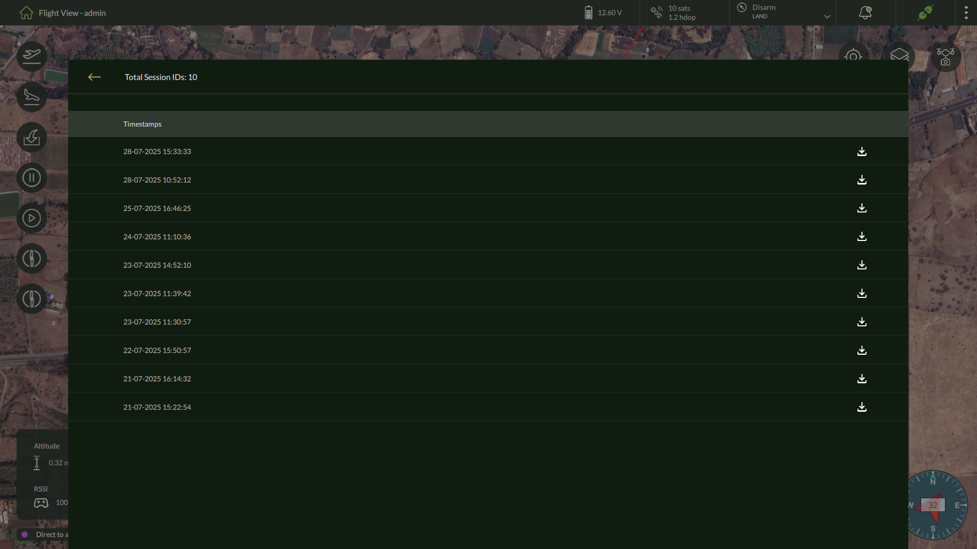
This shows:
- Session timestamps
- Session IDs
- Download option for each log
Viewing Detailed Log Entries
After opening the main System Logs screen, you can view more granular information for any recorded log session.
To access detailed logs for a specific entry:
- On the System Logs table, click the log row you wish to review.
- The application displays a detailed log view listing every recorded event during that session.
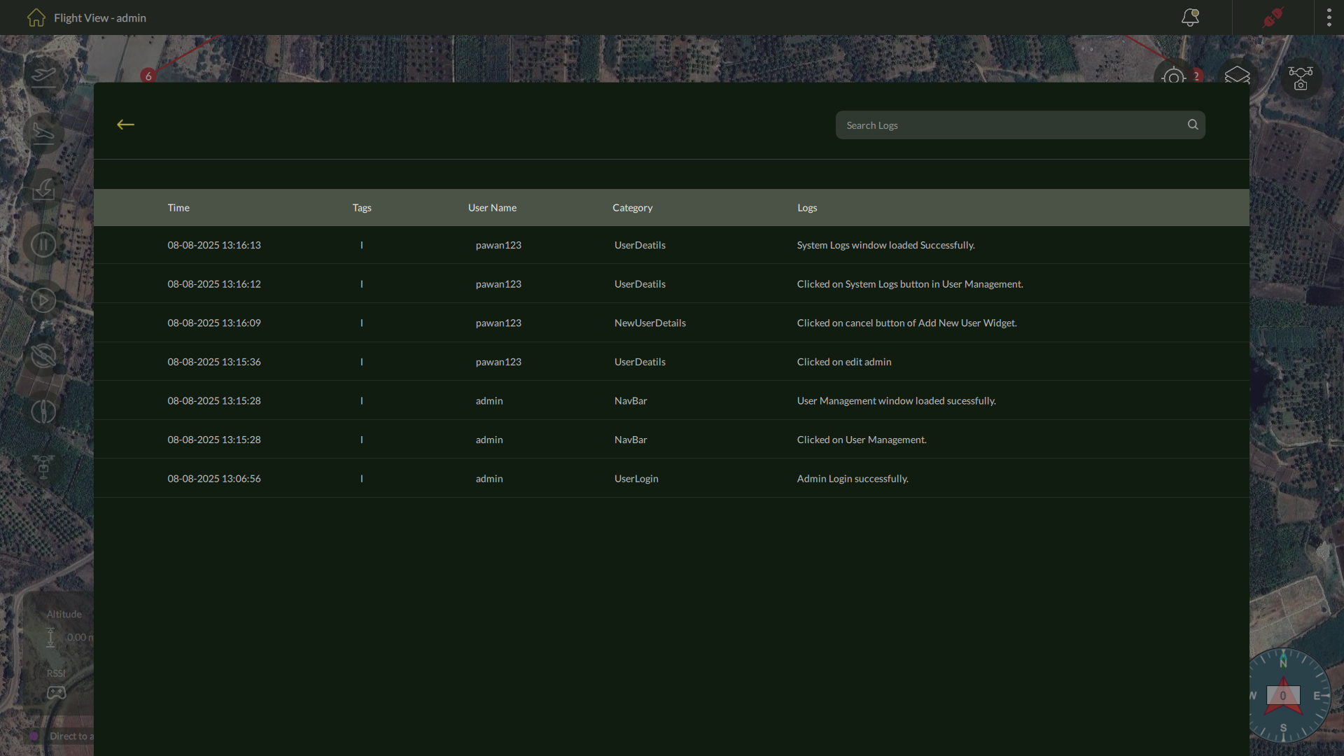
3. Each row shows the following information:
- Time – Timestamp when the event occurred.
- Tags – Associated labels or identifiers.
- User Name – The operator account that performed the action.
- Category – The type of activity (e.g., User Login, NavBar interaction).
- Logs – A description of the event or action taken.
Here on this screen, you can use the search bar at the top right to search for specific logs by entering a keyword or part of the event description.
| Note: This detailed view allows you to audit all user interactions, configuration changes, and critical actions performed during the selected session. |
5.5 General Settings
Overview
Accessing General Settings
To open the General Settings panel:
- From the Home screen, click the three-dot menu located in the top-right corner.
- Select General Settings from the dropdown menu.
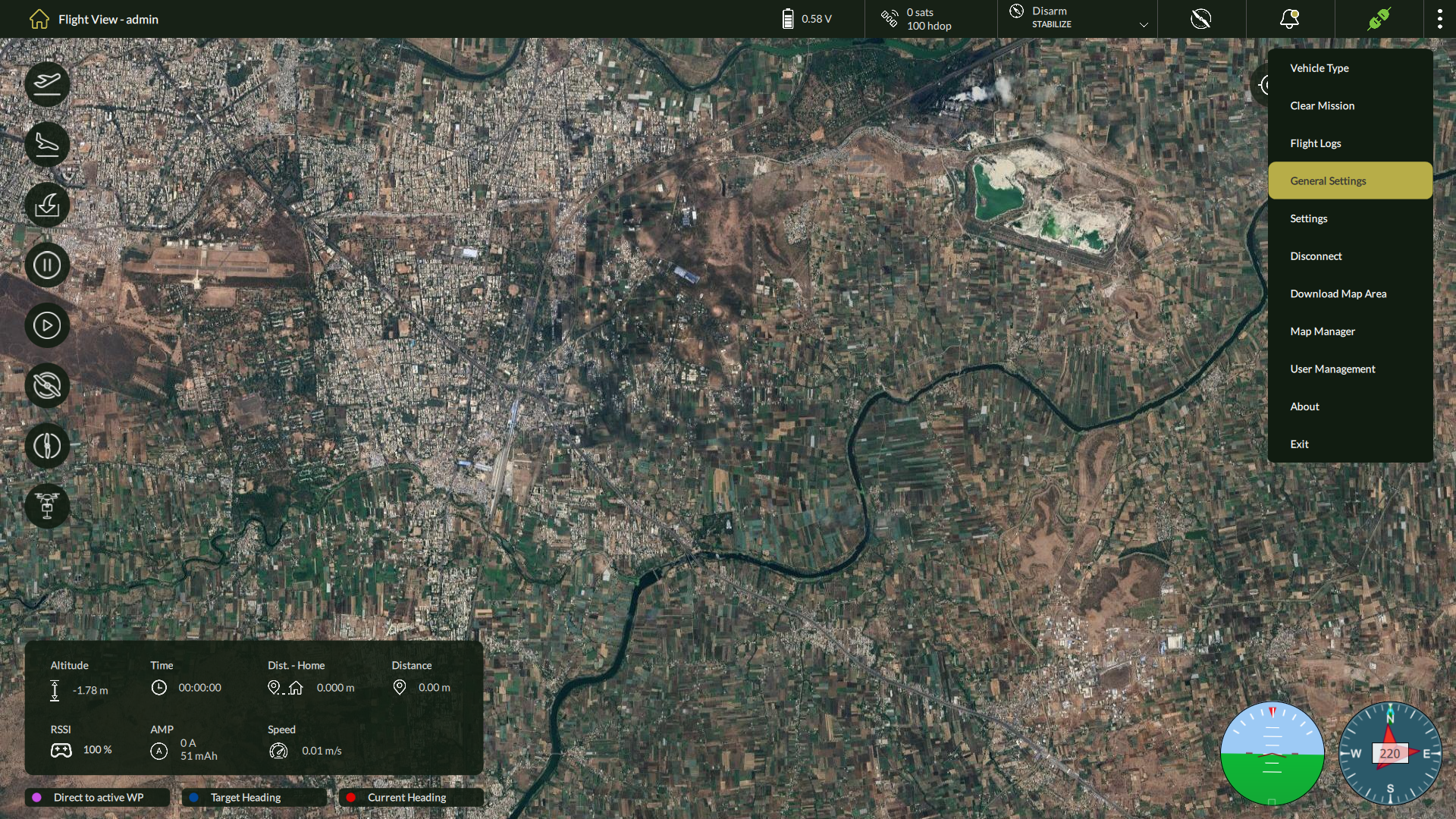
- It will show Unit Settings Screen.
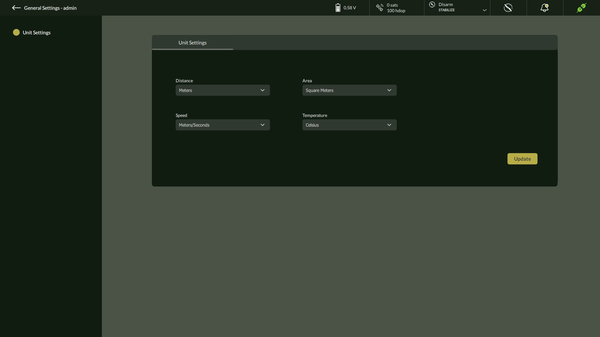
Unit Configuration Options
| Setting | Description | Available Options |
| Distance Unit | Sets the unit for linear measurements such as waypoint distances. | Meter (m), Feet (ft) |
| Speed Unit | Defines the unit for displaying drone velocity. | m/s, km/h, mph |
| Area Unit | Configures how field and mission areas are measured and displayed. | Square Meter (m²), Acre, Hectare |
| Temperature Unit | Determines the unit for temperature readings (used in logs, sensors, etc). | Celsius (°C), Fahrenheit (°F) |
Applying Changes
After selecting appropriate units for each field:
- Click the Update button to apply the changes.
- A confirmation message will appear once the settings are saved successfully.
- The updated units will reflect across all relevant modules, including telemetry, flight view, and mission planning.
| ⚠️ Note: Unit preferences are saved per user and will persist across sessions unless manually changed. |
5.6 Settings
RPA Settings (Admin)
The RPA Settings section provides administrative-level configuration options for camera integration, sensor calibration, joystick setup, gimbal alignment, and critical flight safety controls.
🔗 Drone connection is mandatory to access these settings.
🔒 All users can configure parameters in this section.
To access RPA Settings:
- From the Home screen, click the three-dot menu (top-right).
- Select Settings from the dropdown.
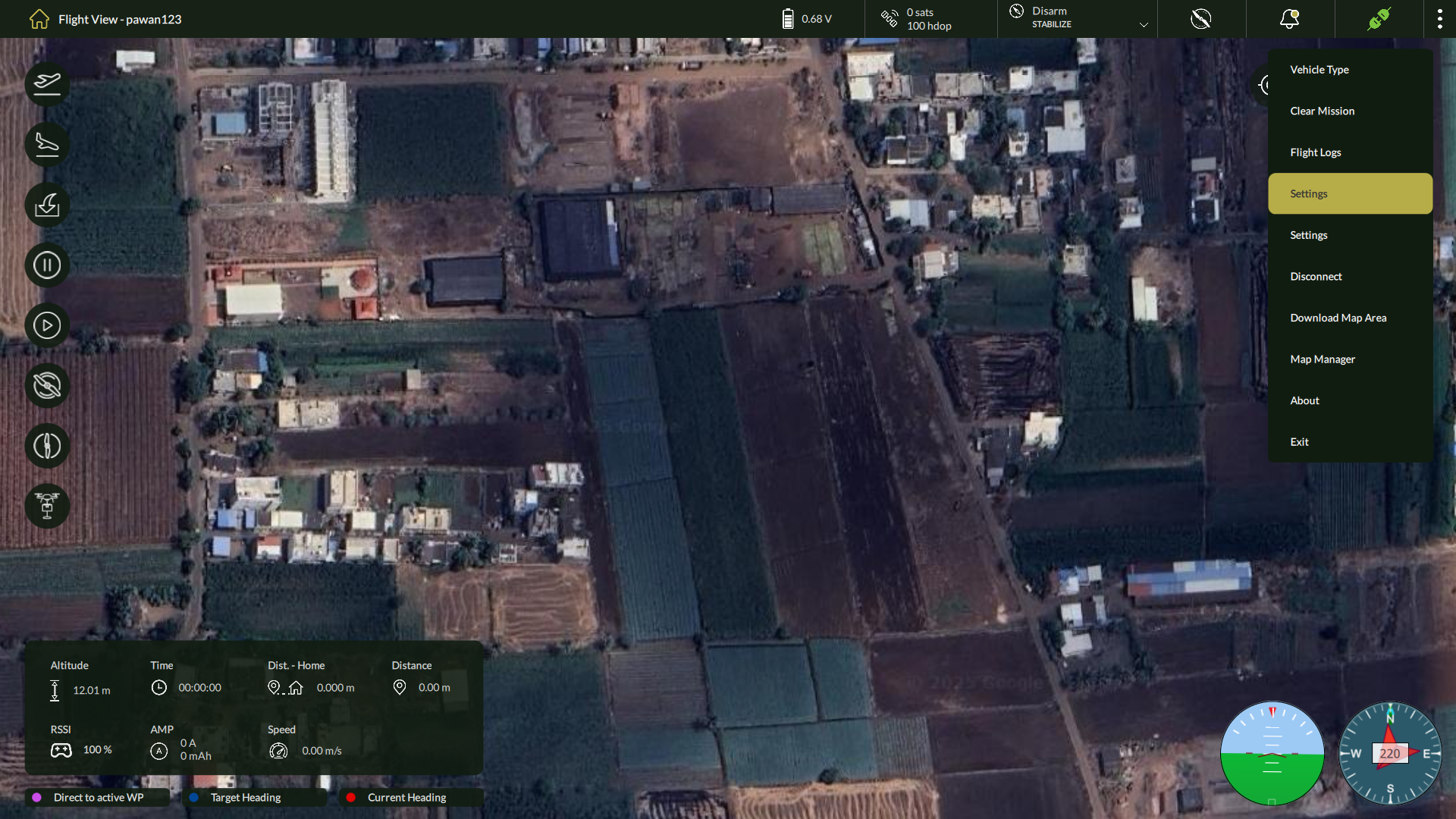
3. Use the left side panel interface to switch between Hardware Setup, Calibration, and Drone Safety.
5.6.1 Hardware Setup
This section provides options to configure physical components such as the camera, gimbal, and joystick.
1. Camera
This section allows you to configure camera settings, add custom cameras, set up video streaming, enable live stream options, and adjust gimbal parameters for optimal camera control.
A. Camera Settings
Step 1: Access Camera Settings
- Navigate to: Settings > Hardware Setup > Camera
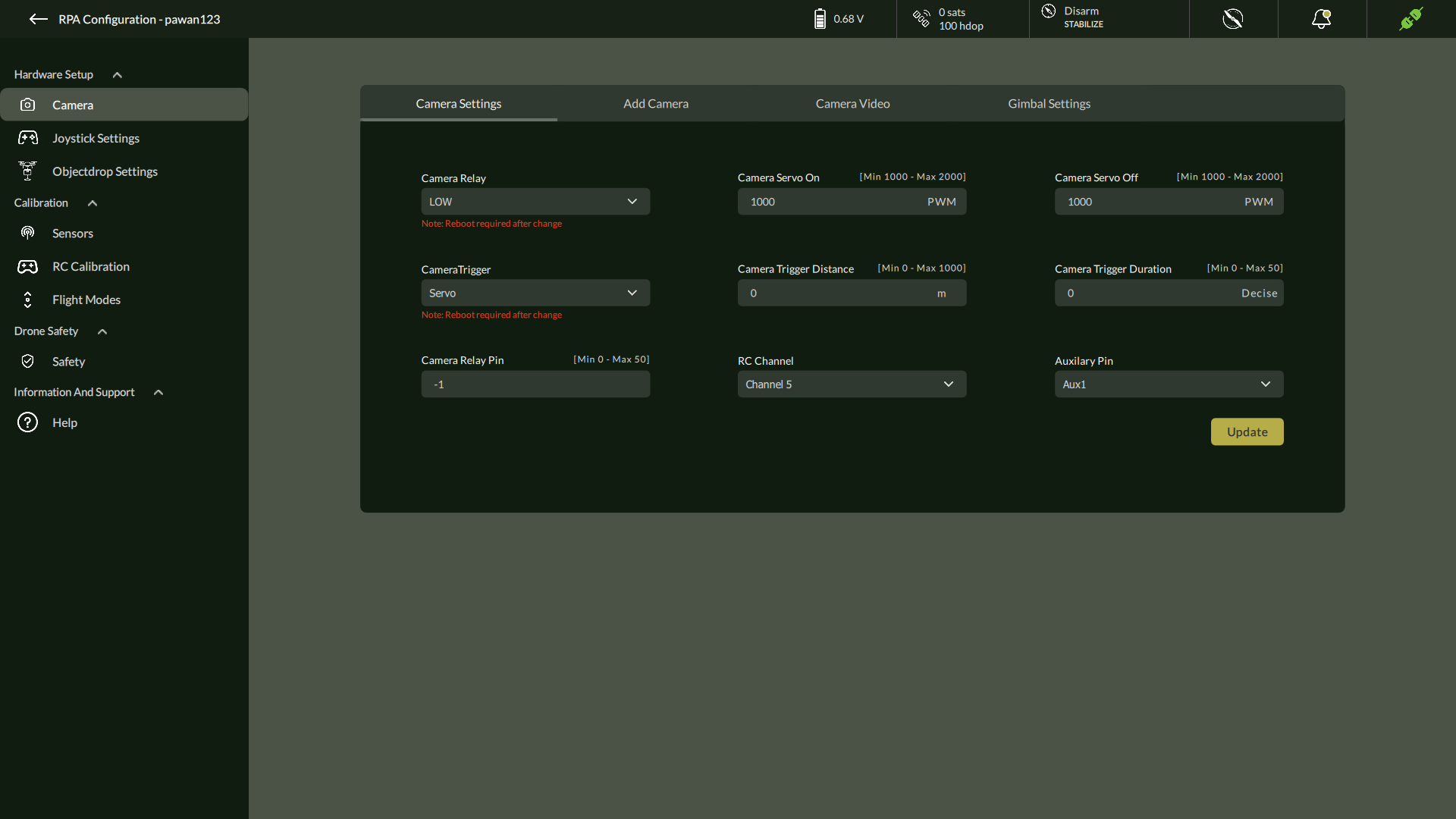
Step 2: Configure Camera Parameters
| Parameter | Description | Range |
| Camera Relay | Relay output behavior | Low / High |
| Camera Servo On/Off | PWM values to trigger camera | 1000 – 2000 |
| Camera Trigger Type | Trigger control mechanism | Servo / Relay |
| Camera Trigger Distance | Auto trigger interval (in meters) | 0 – 1000 |
| Camera Trigger Duration | Duration of trigger (in deciseconds) | 0 – 50 |
| Camera Relay Pin | Assigned output pin | 0 – 50 |
| RC Channel Selection | Channel for manual camera trigger | 1 – 16 |
| Auxiliary Pin | Extra control features (e.g., focus/flash) | 0 – 50 |
Step 3: Apply
- Click Update to save changes to the drone.
B. Add Camera
To configure a custom camera for mission planning and payload optimization, use the Add Camera option under the Hardware section.
Steps to Add a Camera:
- Click “Add Camera”
- Opens the camera configuration panel.
x
- Opens the camera configuration panel.
- Enter Camera Parameters:
Field | Description | Unit | Required |
Camera Type | Select from the dropdown list of supported types (e.g., RGB, Thermal) | — | ✔️ |
Sensor Width | Width of the camera sensor | millimeters (mm) | ✔️ |
Sensor Height | Height of the camera sensor | millimeters (mm) | ✔️ |
Focal Length | Focal length of the lens | millimeters (mm) | ✔️ |
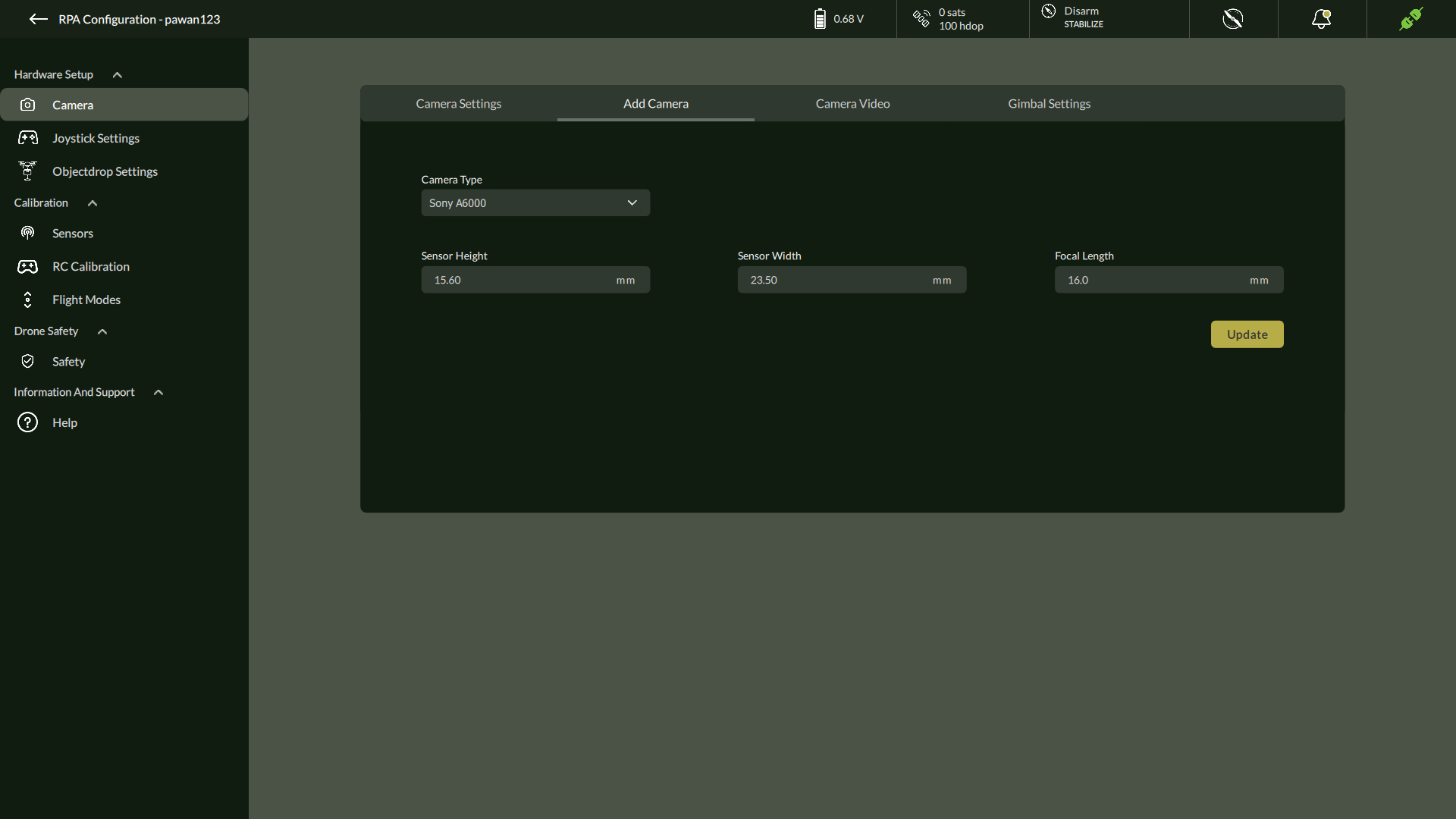
- Save Camera
- Click Update to confirm.
- The newly added camera will be available for mission calculations (e.g., Ground Sampling Distance, coverage estimation).
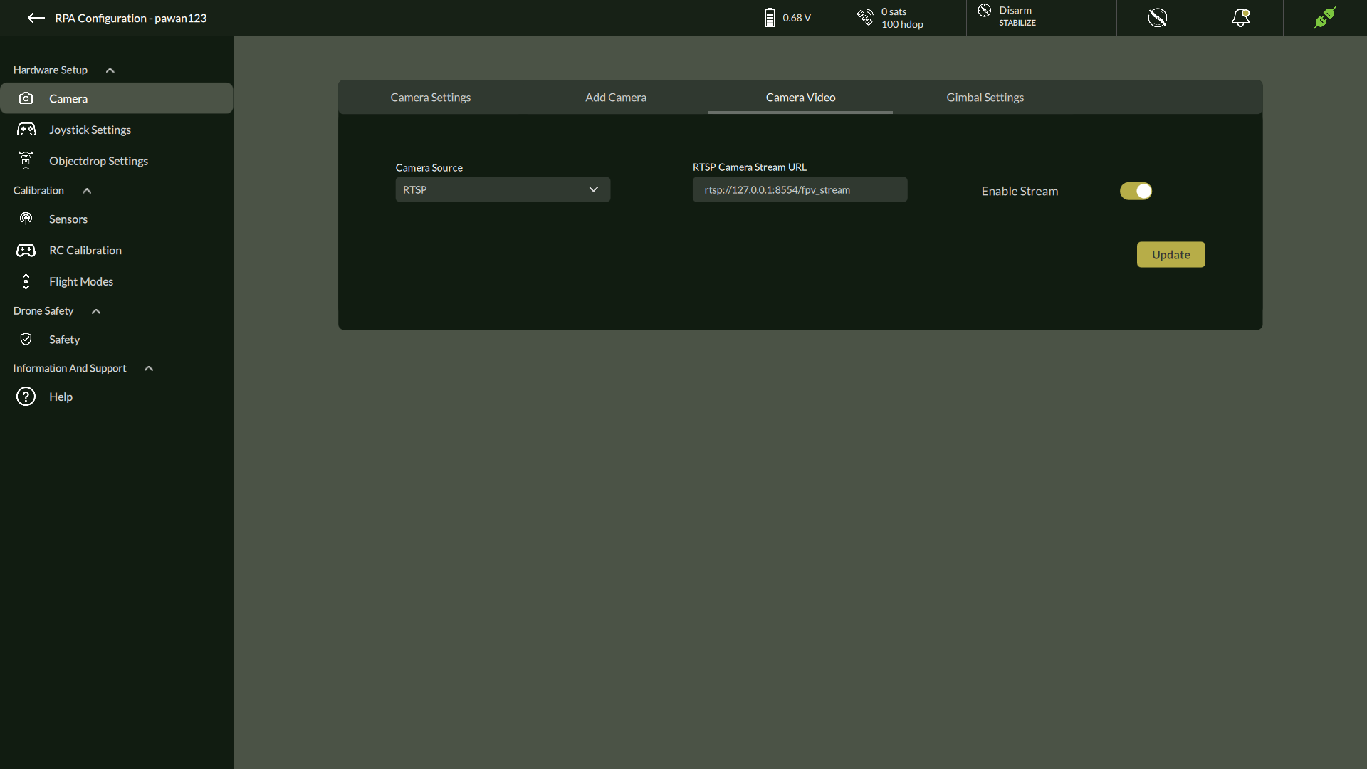
C. Camera Video
Configure video streaming from USB or RTSP-compatible cameras.
Steps:
- Navigate to Settings > Hardware Setup > Camera > Camera Video
- Select Camera Source: USB / RTSP / Disable
- If RTSP, enter the Stream URL (e.g., rtsp://<IP>:<PORT>/stream)
- Toggle Enable Stream ON/OFF
- Click Update
D. Gimbal Settings
Control and stabilize camera orientation with 3-axis gimbal setup.
Steps:
- Go to Settings > Hardware Setup > Gimbal
- Configure each axis: Tilt, Roll, Pan
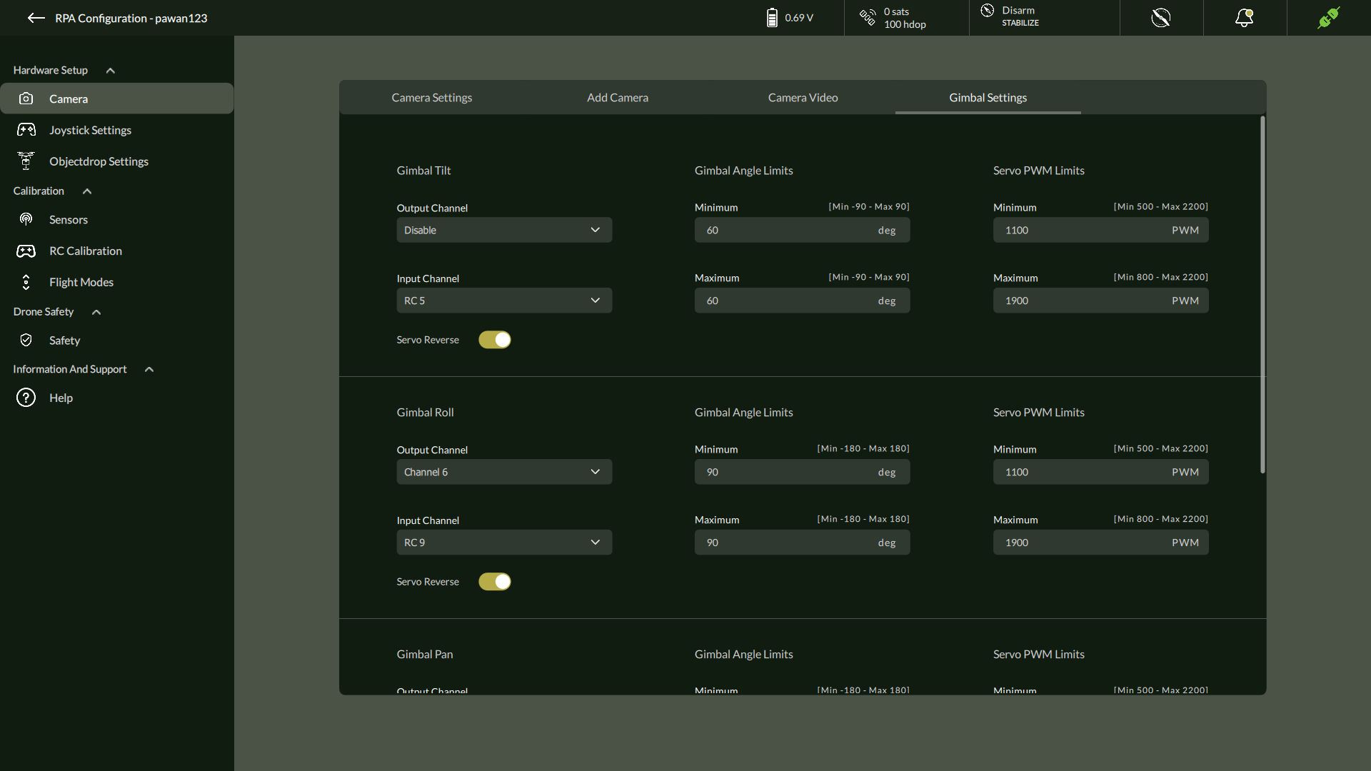
| Setting | Description | Range |
| Output/Input Channel | Servo control mapping | Dropdown options |
| Servo Reverse | Enable/Disable direction inversion | Toggle |
| Gimbal Angle Limit | Motion range | Tilt: ±90°, Roll/Pan: ±180° |
| Servo PWM Limit | Servo signal limit | 500 – 2200 PWM |
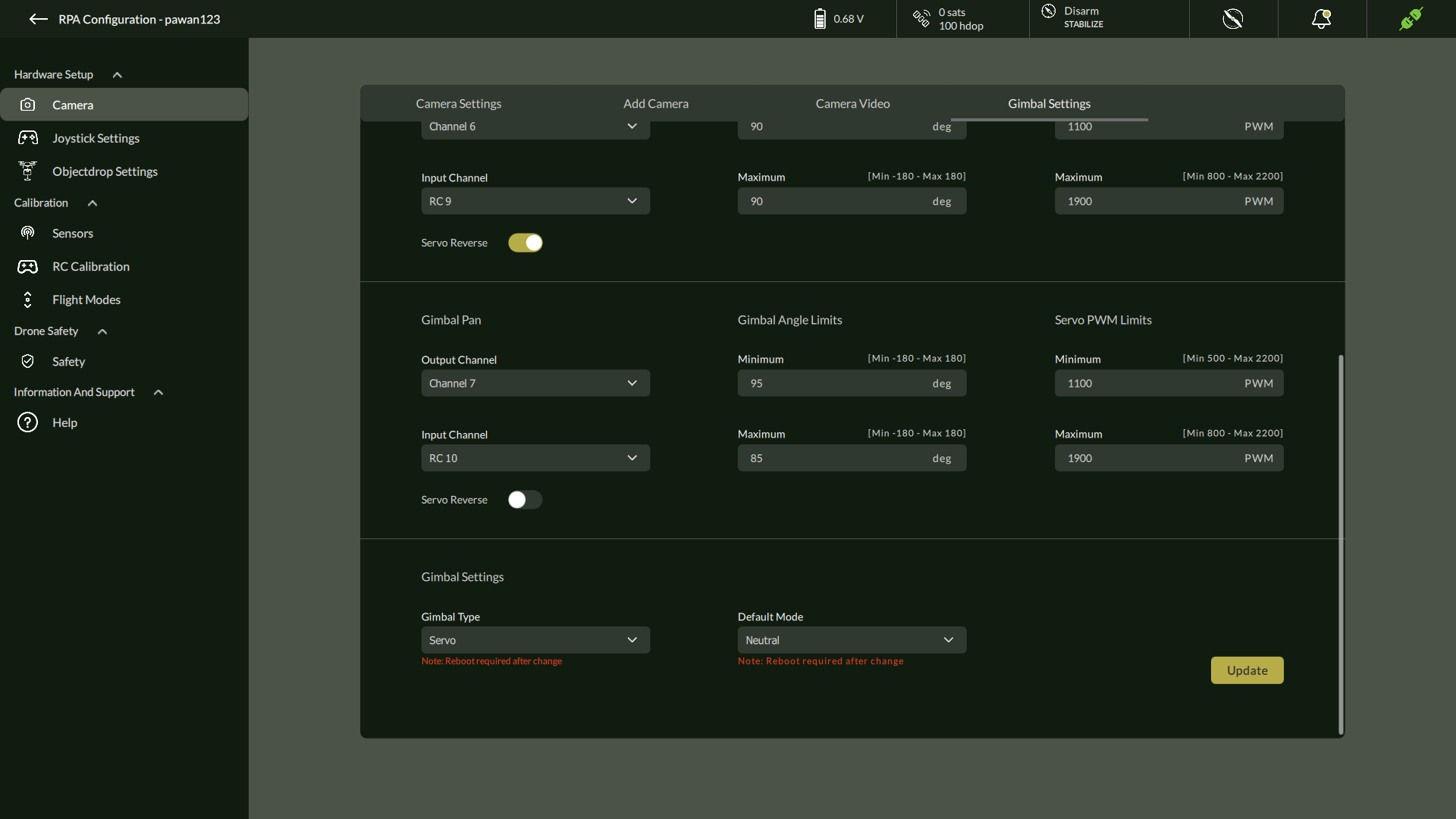
After configuration, click Update.
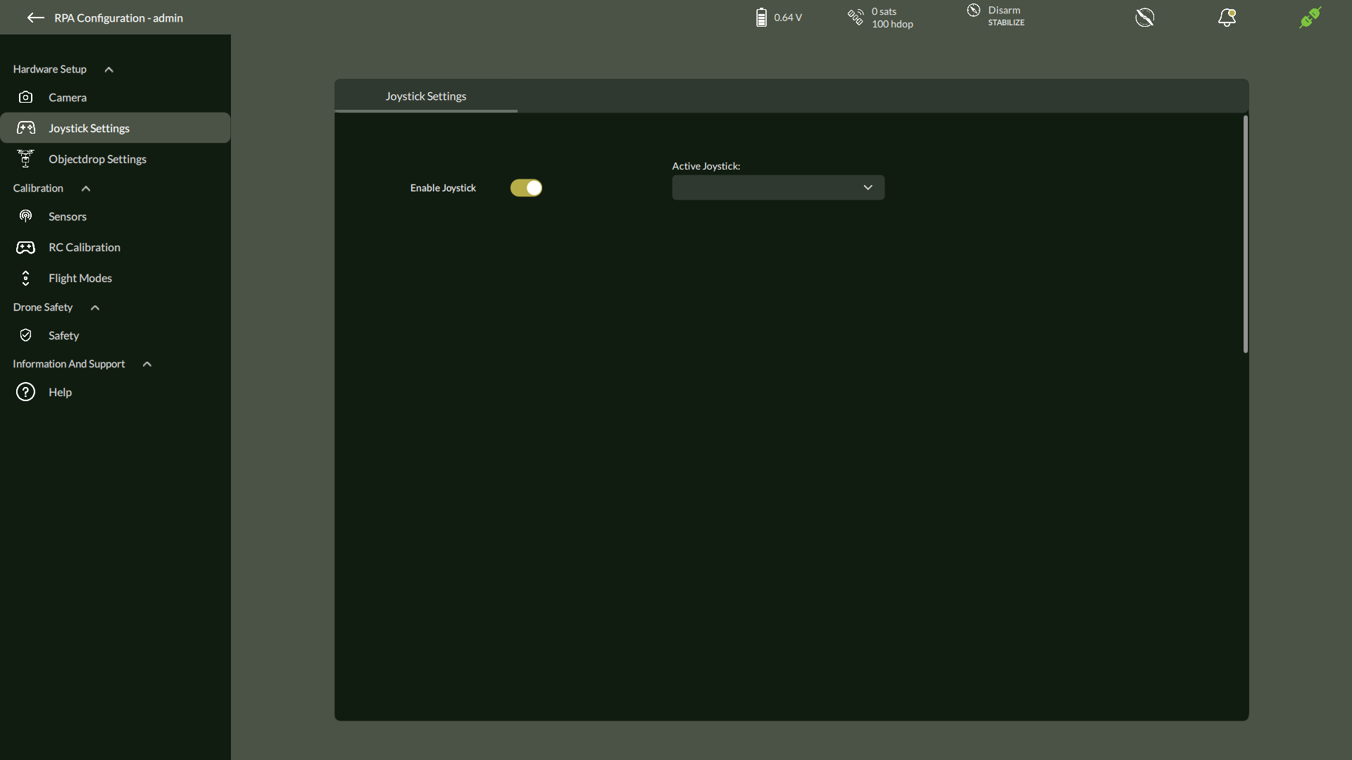
2. Joystick
Configure physical joystick device for drone control.
Steps:
- Navigate to Settings > Hardware Setup > Joystick
- Enable Joystick
- Select Active Joystick
- Click Start to assign buttons for:
- Reverse, Center positions
- Use Next, Skip, Cancel as needed
- Click Update
- Reboot joystick when prompted
3. Object Drop Settings
The Object Drop Settings screen allows the user to configure which auxiliary pin on the flight controller will be used to trigger the object drop mechanism during flight operations.
Use Case: This configuration is essential when the drone is equipped with an object dropping payload, such as supply packages, sensors, or beacons in defence or rescue missions.
Accessing Object Drop Settings
To configure the Object Drop feature:
- Navigate to the Settings menu by clicking the three-dot menu from the Flight View.
- In the RPA Settings screen, go to the Hardware Setup
- Select Object Drop Settings from the list.
This opens the Object Drop Settings panel as shown below:
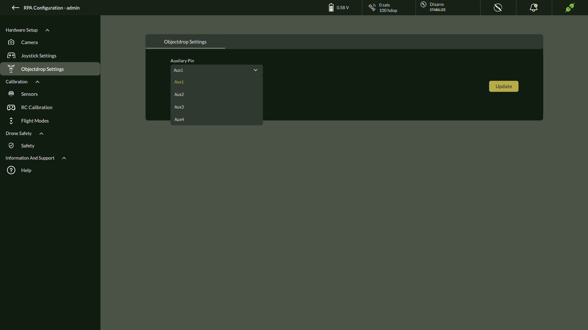
Assigning Auxiliary Pin to Object Drop Mechanism
Configuration Steps
- In the Auxiliary Pin dropdown, select the pin that will be used to trigger the object drop action.
- Available options include: Aux1, Aux2, Aux3, Aux4.
- Available options include: Aux1, Aux2, Aux3, Aux4.
- After selecting the appropriate pin, click the Update
- A confirmation dialog appears stating that the parameters have been successfully updated.
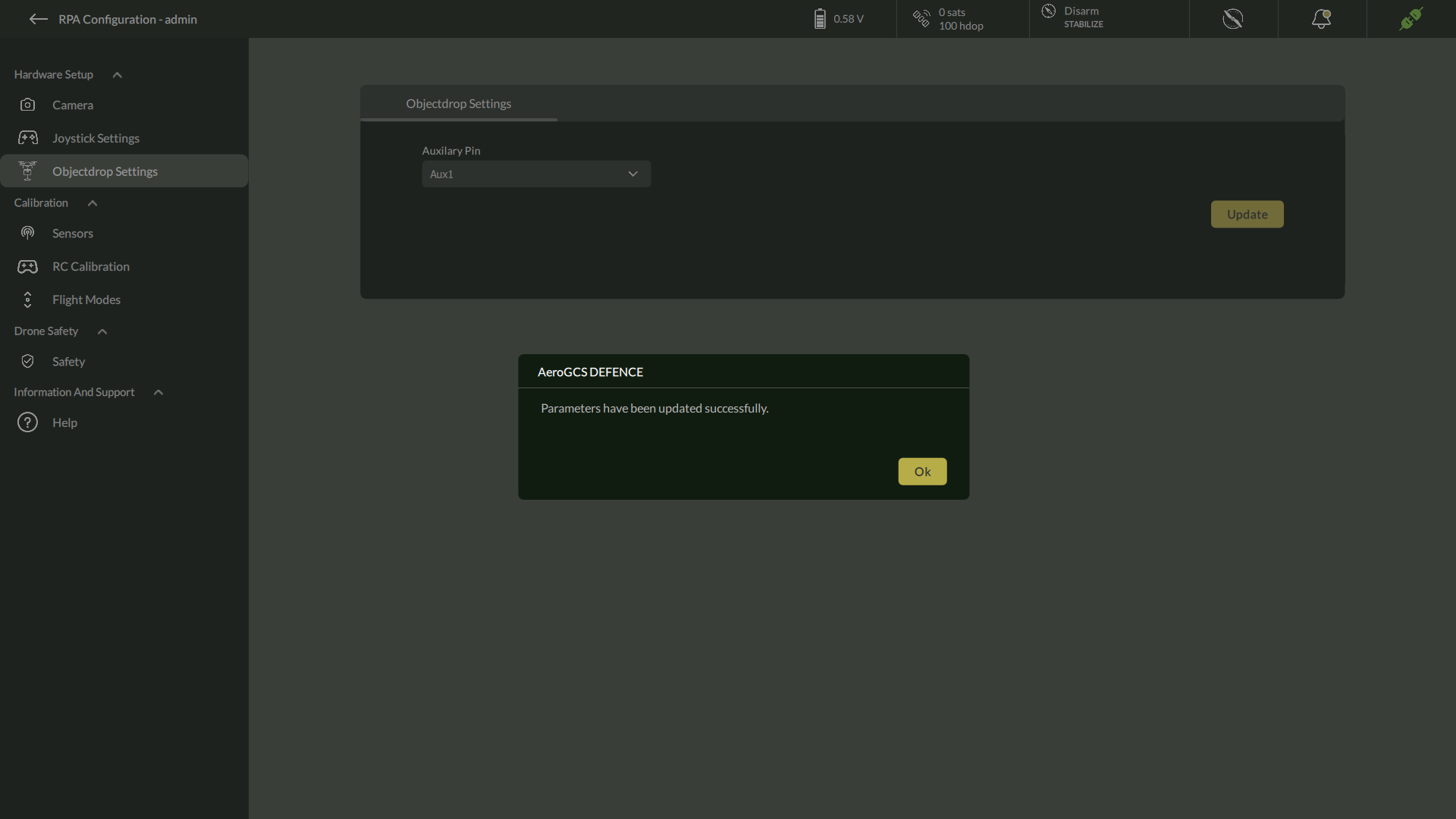
| Note: No reboot is required after configuring the Object Drop Settings. Changes take effect immediately. |
5.6.2. Calibration
Perform sensor alignment and control calibration to ensure optimal drone performance.
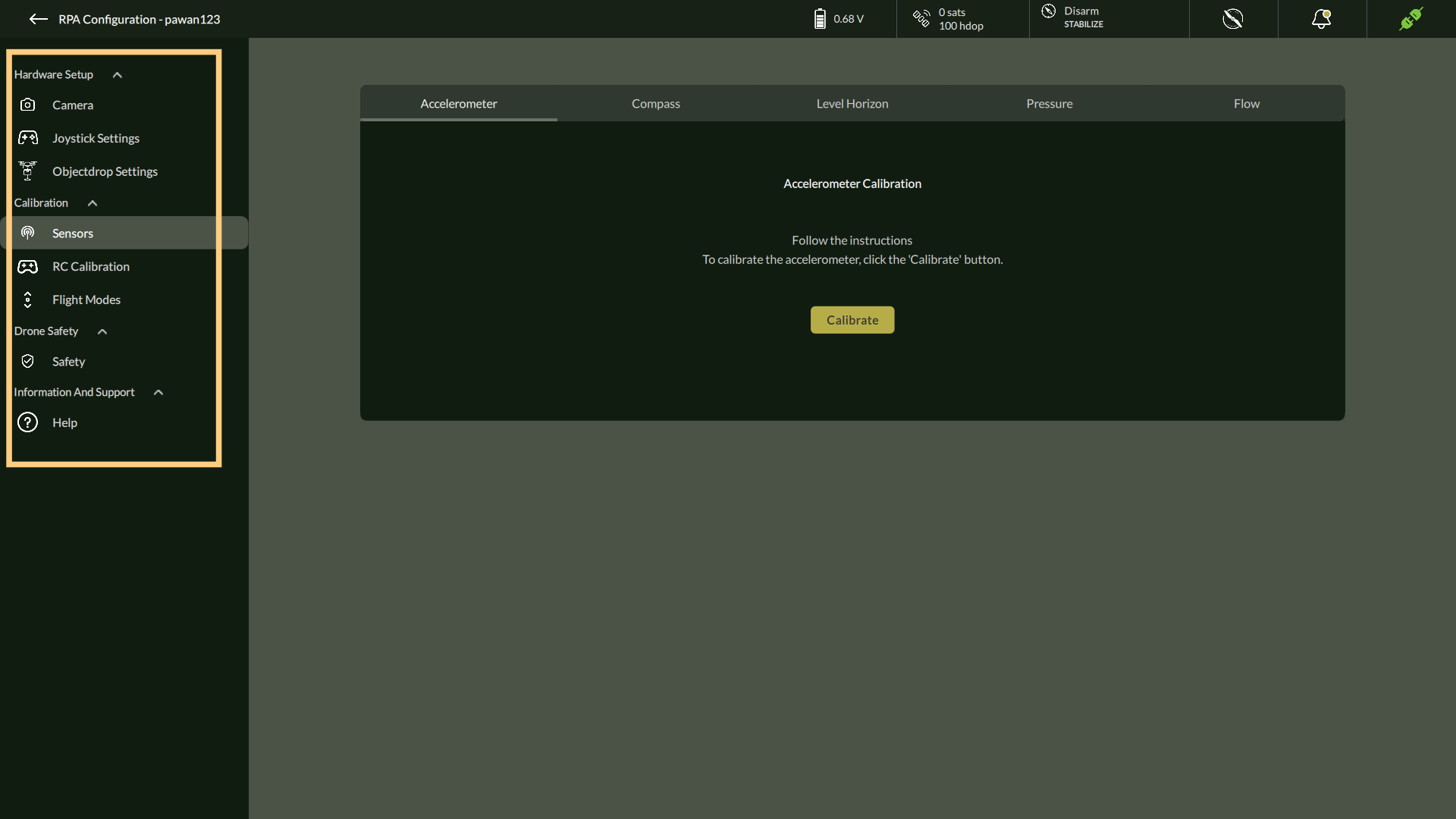
A. Accelerometer Calibration
To perform precise accelerometer calibration for your drone, follow these steps carefully. This process ensures accurate stabilization and orientation detection.
- Navigate to the Calibration Menu
- Go to Settings > Calibration > Accelerometer.
- The Accelerometer Calibration window will appear.
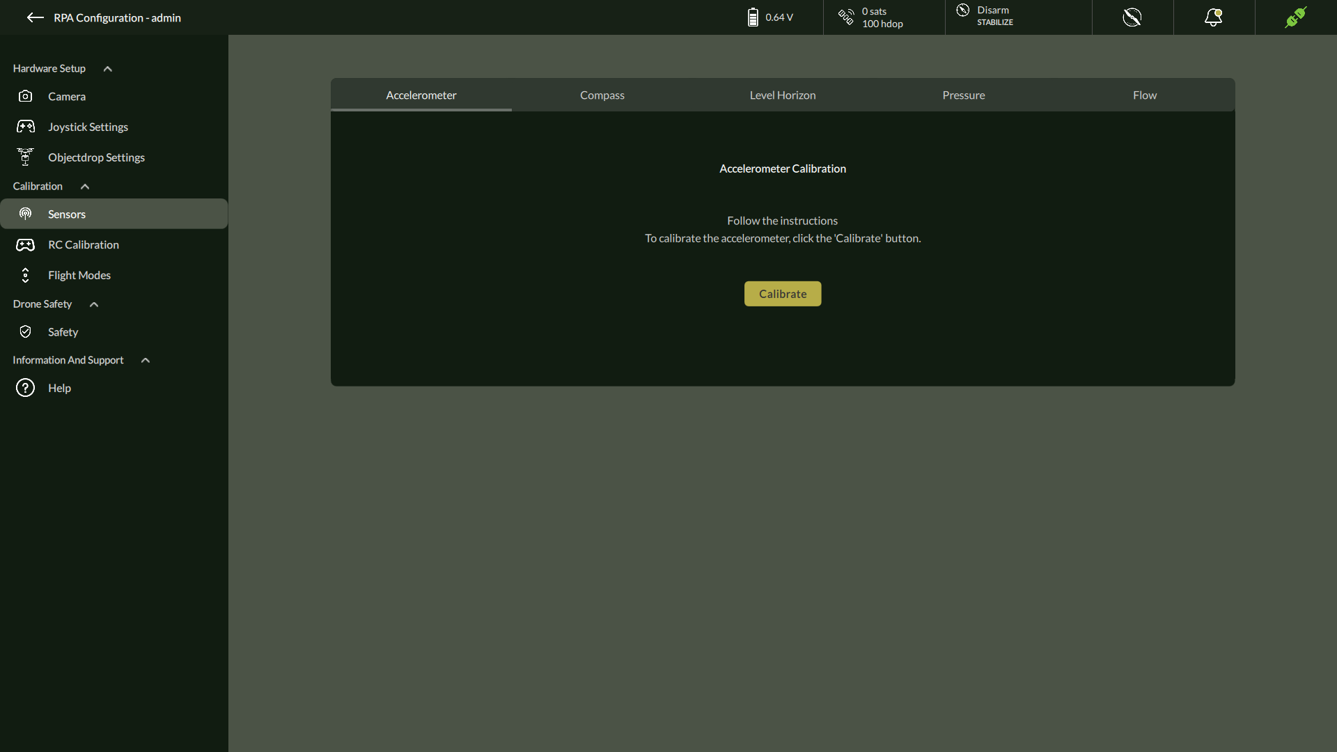
- Start Calibration
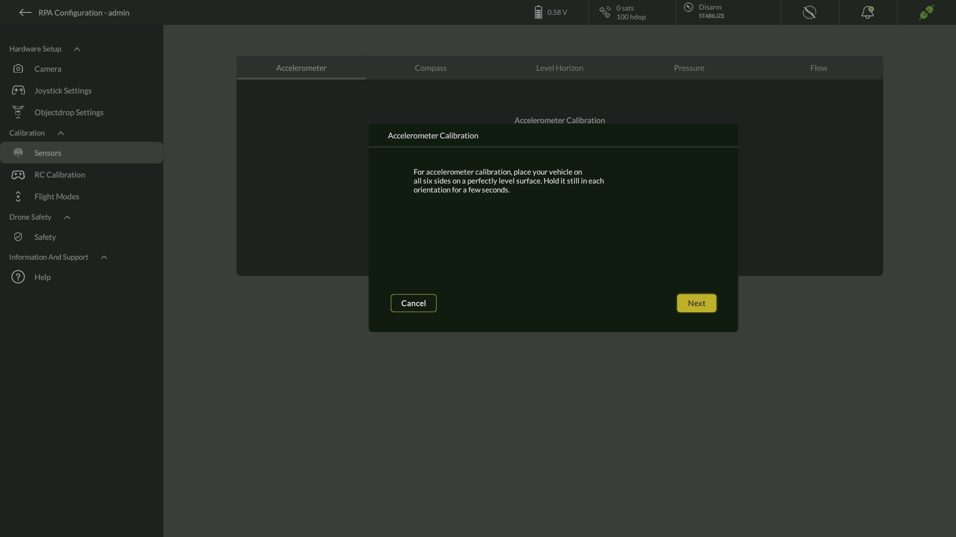
- Click Calibrate.
- A dialog will appear explaining the procedure:
For accelerometer calibration, place your vehicle on all six sides on a perfectly level surface. Hold it still in each orientation for a few seconds.
- Click Next to begin.
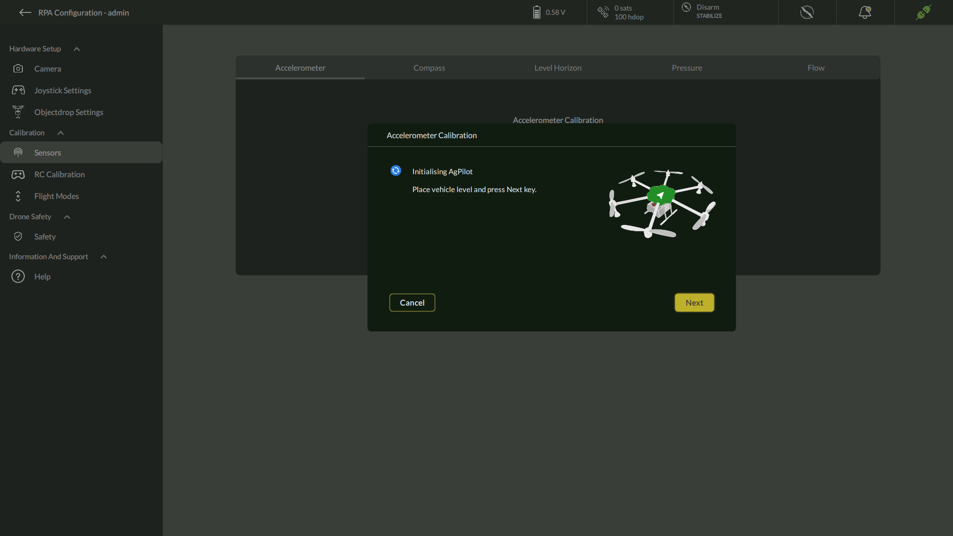
3. Initialize Level Position
- The screen will prompt:
Initializing AgPilot – Place vehicle level and press Next.
- Position the drone in its level (upright) orientation on a stable, flat surface.
- Click Next to confirm.
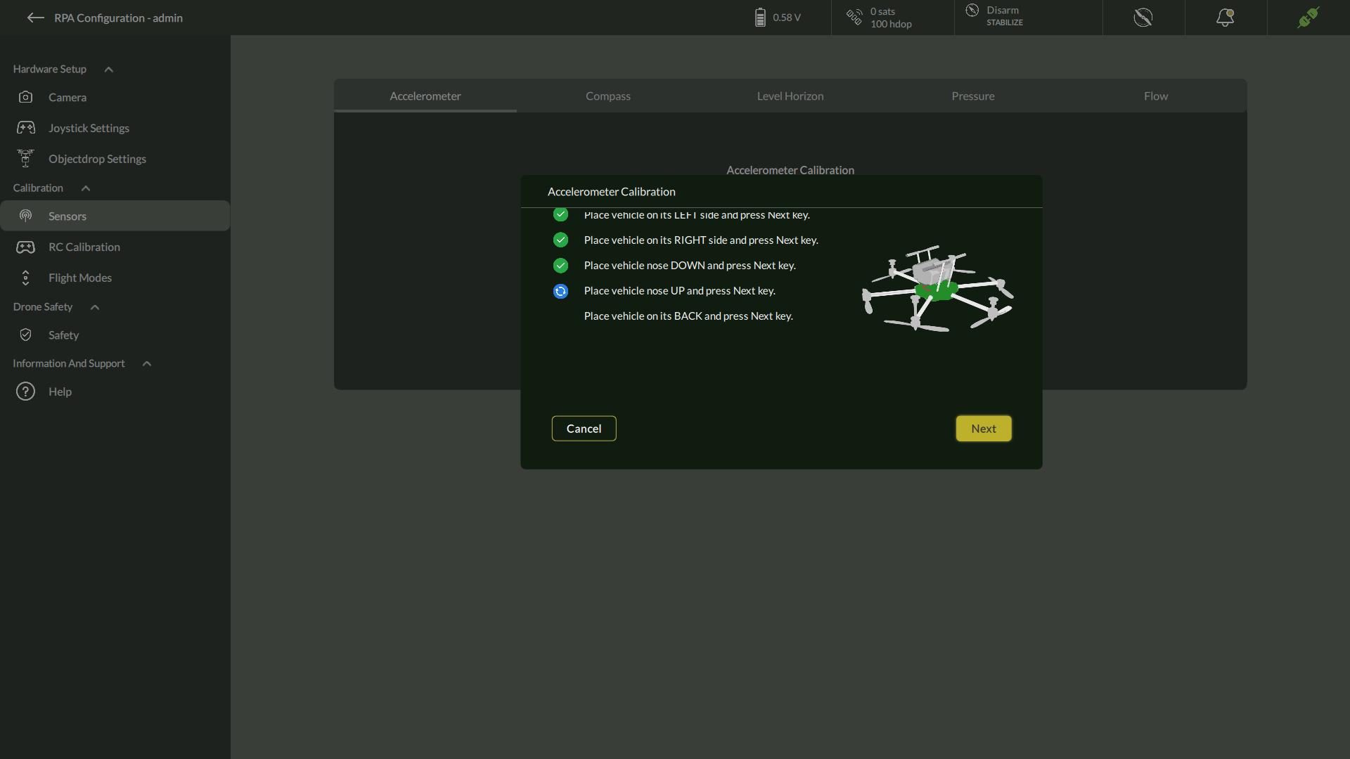
4. Perform Six-Side Calibration
- Follow the sequential instructions shown on-screen. For each pose:
- Place the drone as directed (e.g., left side, right side, nose down, nose up, back).
- Hold the drone still for a few seconds to register the orientation.
- Click Next after each position.
- The calibration checklist will update as you progress through all six orientations.
- Follow the sequential instructions shown on-screen. For each pose:
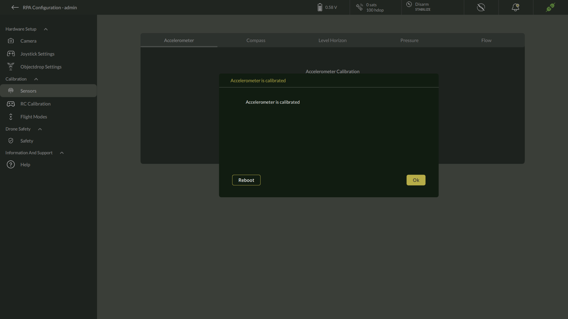
5. Complete Calibration
- After completing all orientations, a confirmation message will appear:
Accelerometer is calibrated.
- At this stage, you must either:
- Click Reboot to restart the flight controller for calibration to take effect, or
- Click OK if prompted, to exit without rebooting immediately.
Important Notes
- Always perform calibration on a flat, stable surface free of vibration or tilt.
- Hold the vehicle steady during each orientation to avoid inaccurate readings.
- A reboot is recommended after calibration to ensure all changes are applied correctly.
B. Compass Calibration
Compass calibration ensures accurate heading determination and stable flight behavior. Follow these steps to calibrate all available compasses and validate their orientation.
Steps to Calibrate the Compass
- Access Compass Calibration
- Navigate to Settings > Calibration > Compass.
- The Compass Calibration screen displays:
- Compass Declination input
- Compass Fitness selector
- List of available compasses with IDs
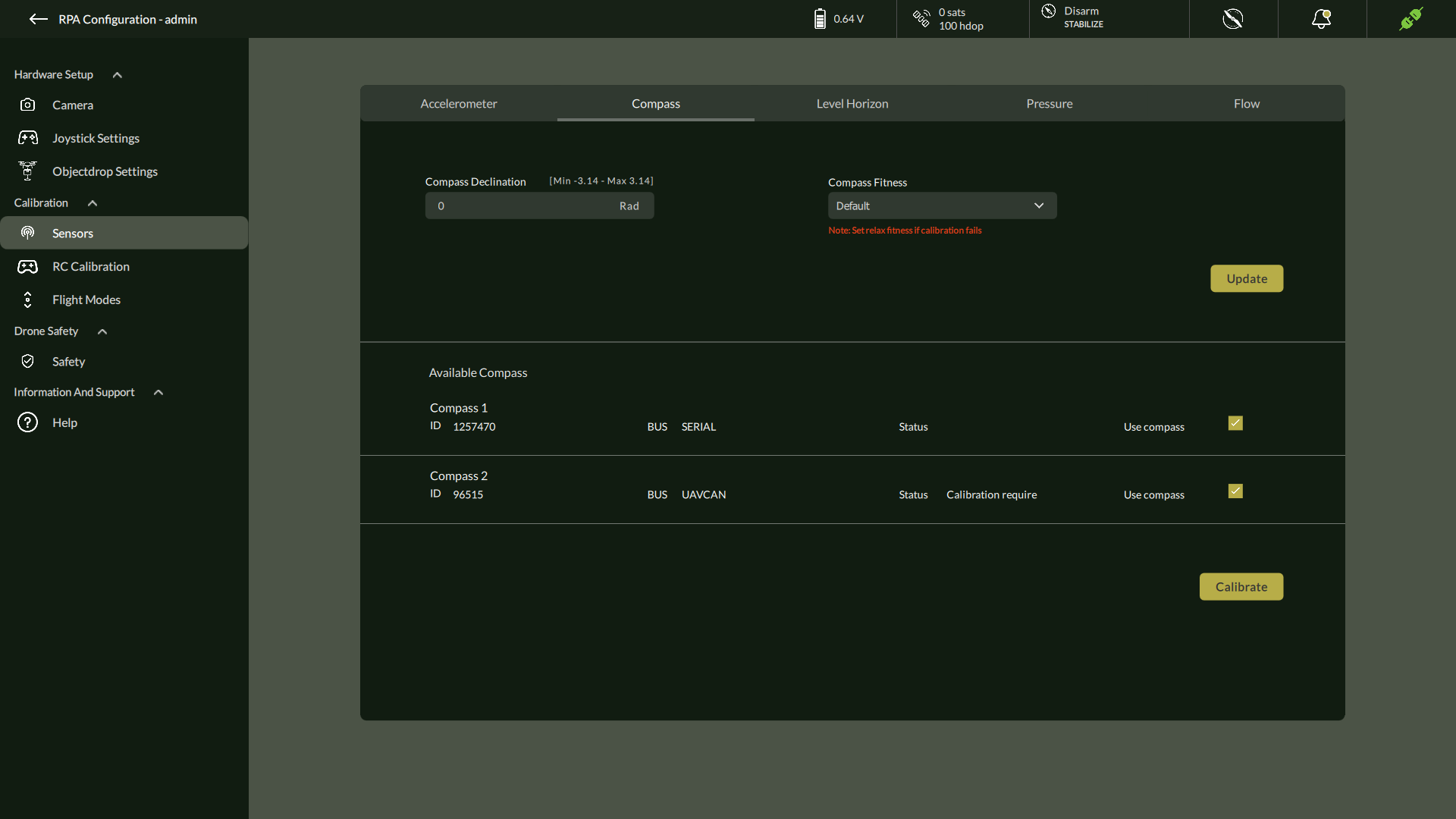
2. Configure Declination and Fitness
- Enter the Compass Declination value if applicable.
- Select Compass Fitness mode:
- Strict (default) – recommended for precise calibration.
- Relaxed – use only if calibration repeatedly fails in Strict mode.
- Click Update.
3. Initiate Calibration
- Select the compass to calibrate, or enable checkboxes to calibrate multiple compasses simultaneously.
- Click Calibrate.
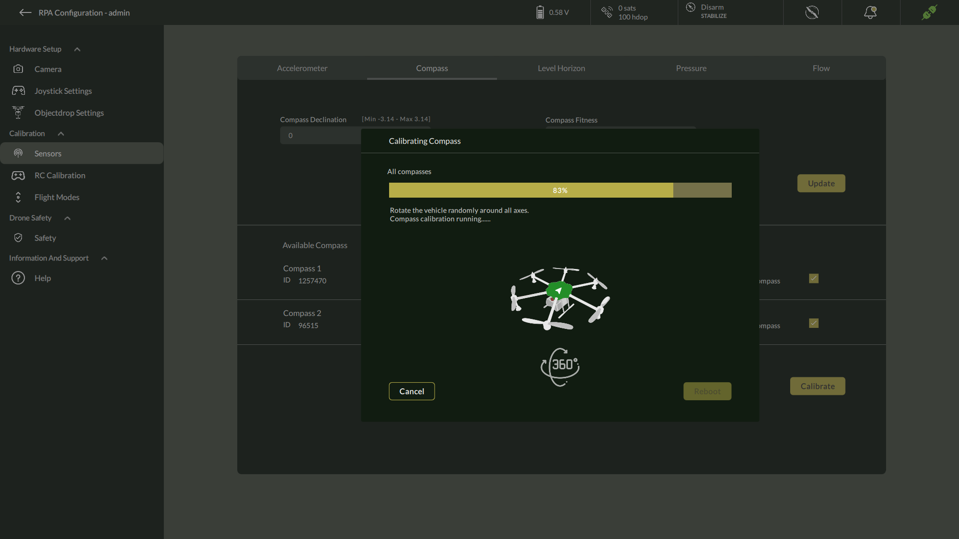
- The calibration window opens, displaying:
- Compass is calibrated status bar initialized at 0%.
- Instruction to begin rotating the vehicle.
- Click Calibrate Button.
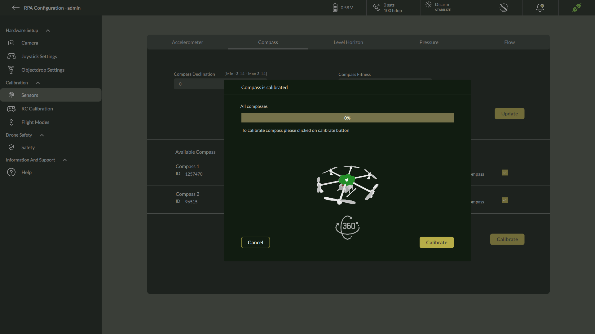
4. Rotate the Drone
- Slowly rotate the drone randomly around all axes, as shown in the on-screen illustration.
- Observe the progress bar indicating calibration percentage.
- Continue rotating until the calibration reaches 100%.
5. Review Orientation Results
- Upon completion, the screen shows:
- Compass is calibrated confirmation.
- Orientation data for each magnetometer (e.g., Mag(0) good orientation: 0 38.5).
- Upon completion, the screen shows:
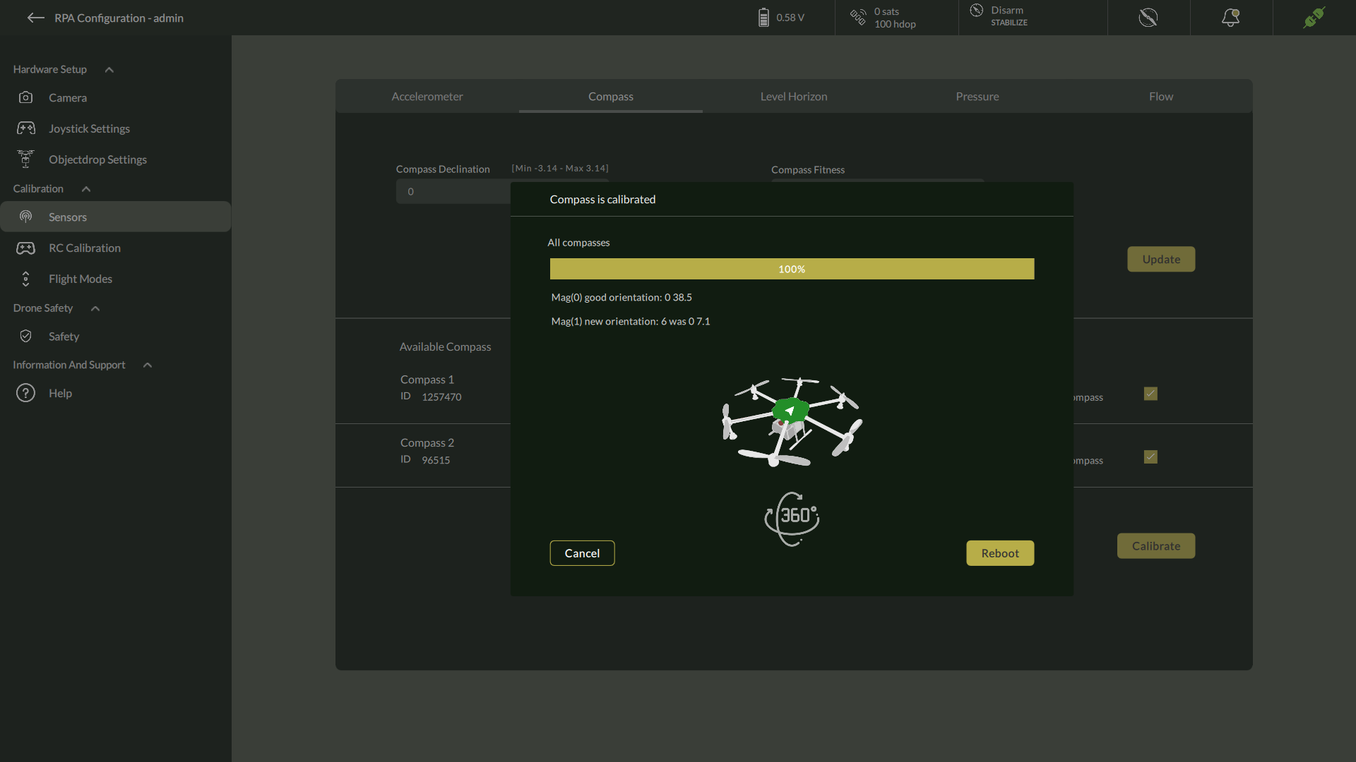
6. Reboot
Click Reboot to restart the vehicle and apply the new calibration.
| Note: If calibration fails or orientation results are inconsistent, set Compass Fitness to Relaxed and repeat the process, ensuring the drone is away from metallic surfaces and strong magnetic fields. |
C. Level Horizon
Level Horizon calibration ensures the autopilot knows the correct level attitude for stable flight.
Steps to Calibrate Level Horizon
- Navigate to Level Horizon
- Go to Settings > Calibration > Level Horizon.
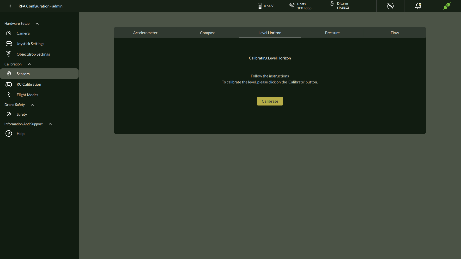
2. Prepare the Drone
- Ensure the vehicle is placed flat and stable on a level surface.
3. Start Calibration
- Click Calibrate to begin the process.
4. Follow On-Screen Instructions
- The calibration dialog guides you step by step:
- Hold the vehicle in its level flight position.
- Initialising AgPilot.
- Level Horizon Completed.
- You will see a confirmation screen showing the trim values for roll, pitch, and yaw.
- The calibration dialog guides you step by step:
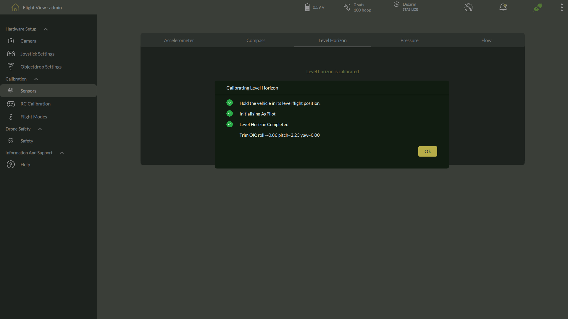
5. Verify Completion
- Confirm that the message Trim OK displays acceptable values (close to zero).
- Click OK to close the dialog.
| Note: If trim values are significantly off, repeat calibration and verify the surface is level. |
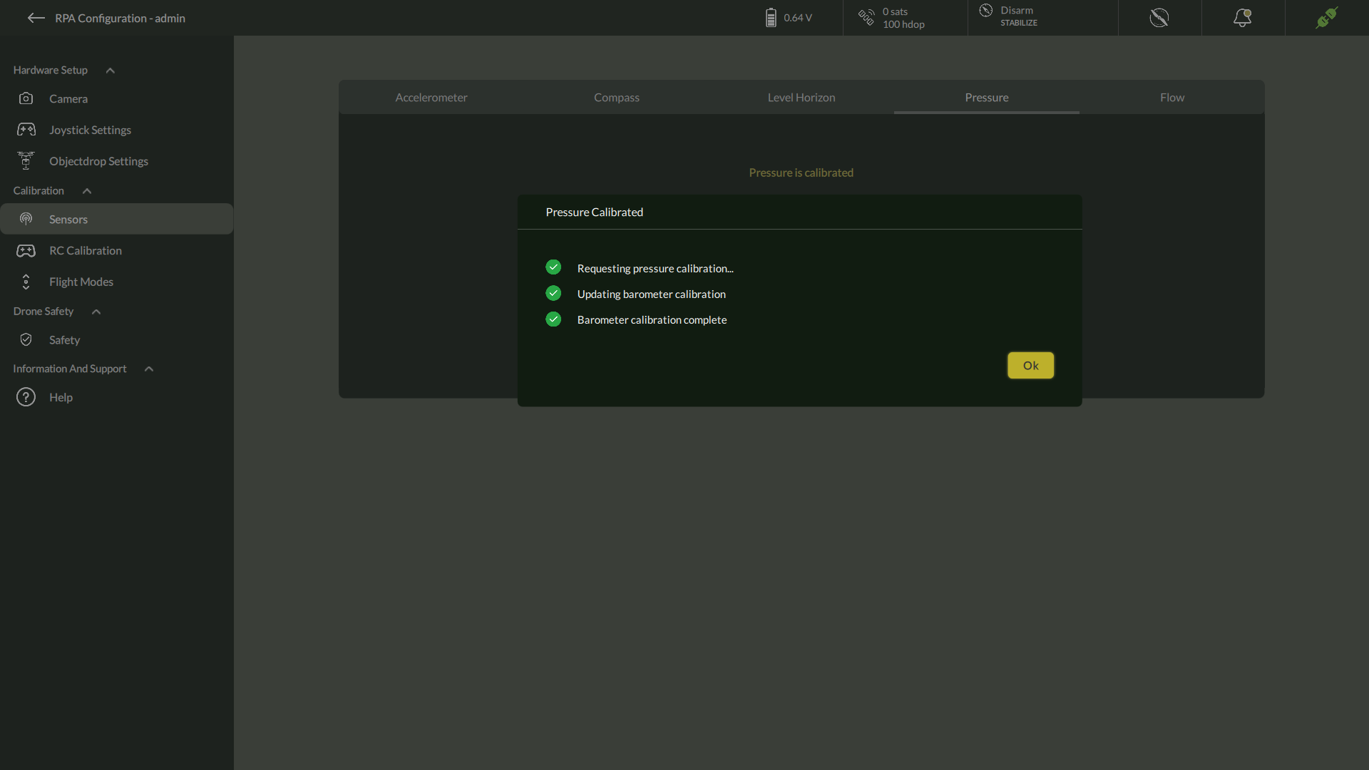
D. Pressure Sensor
- Navigate to Settings > Calibration > Pressure
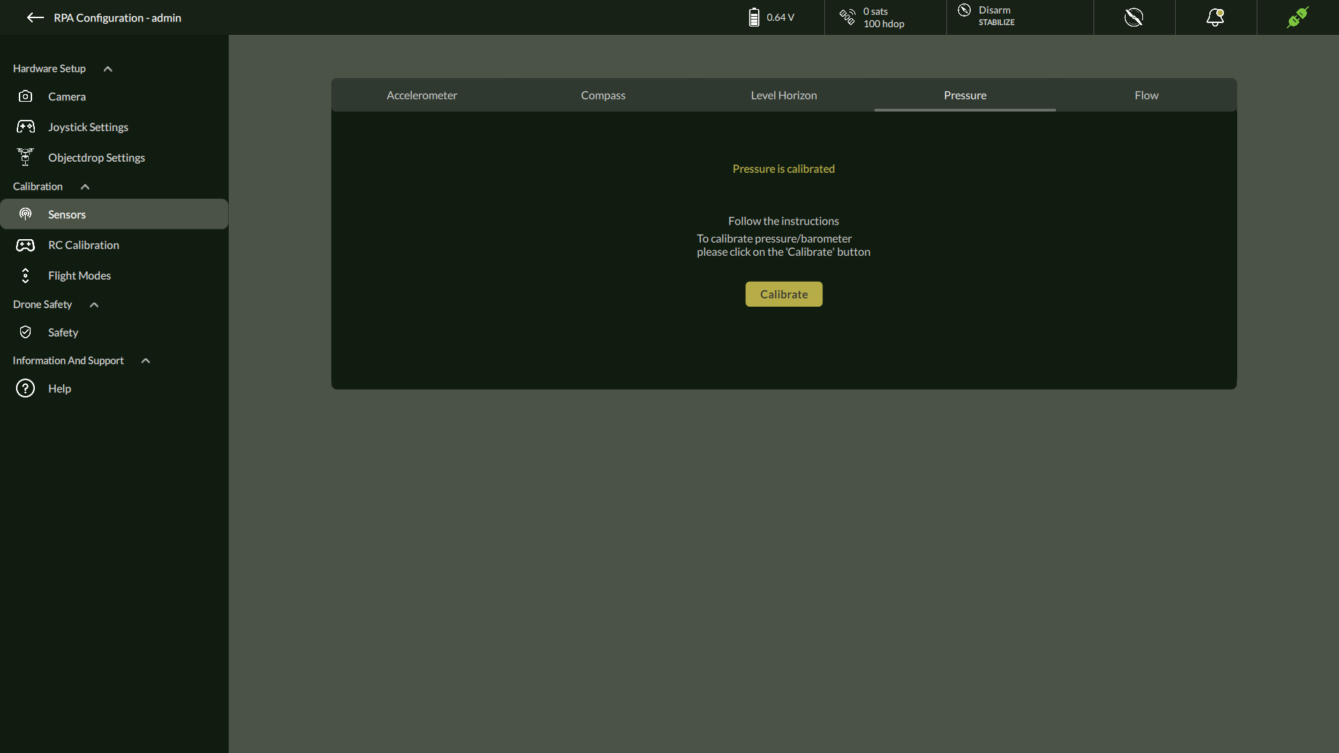
2. Click Calibrate to calibrate pressure/barometer
3. After Calibration completes it shows Pressure Calibrated.
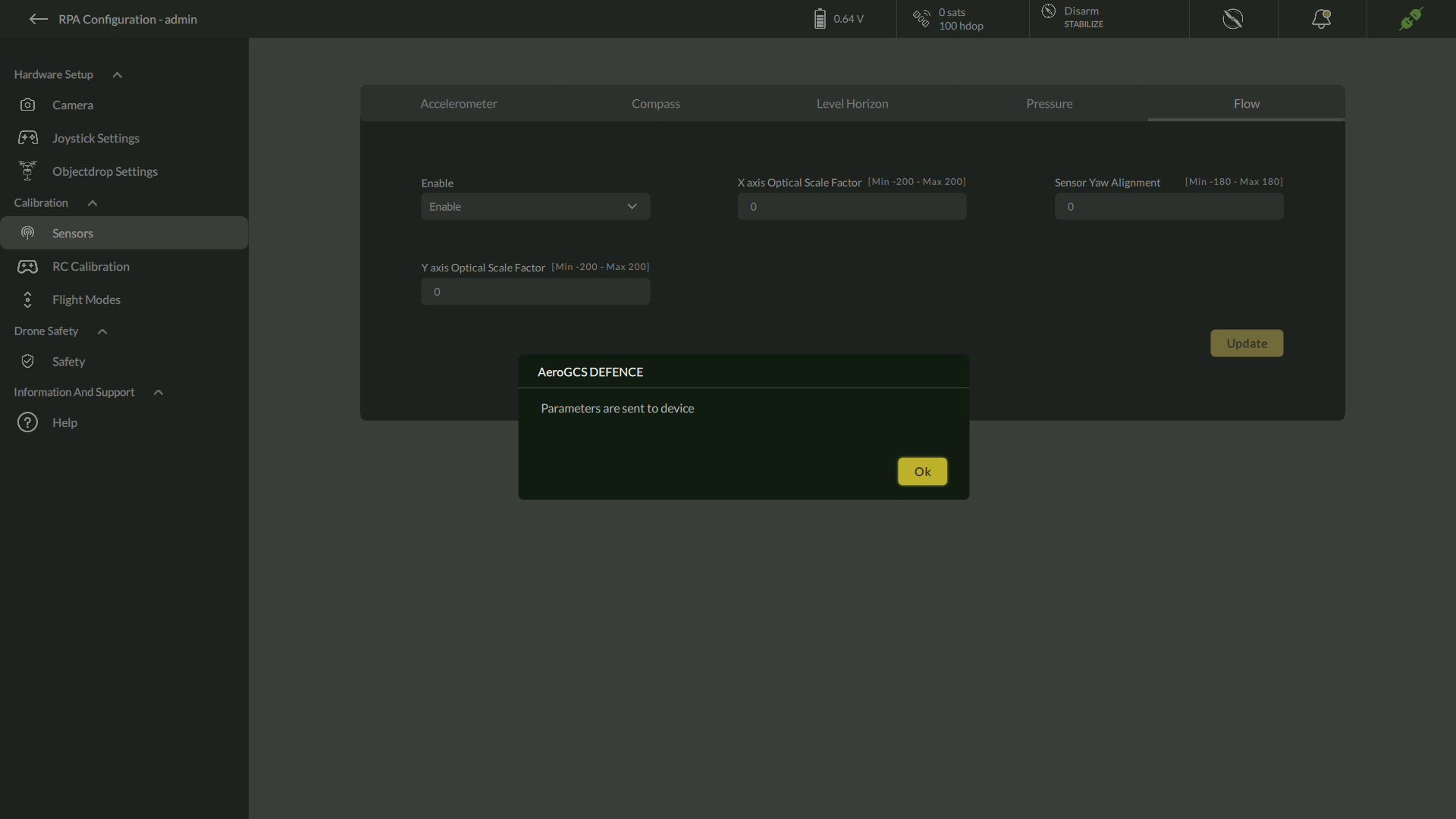
E. Flow Sensor Settings
- Navigate to Settings > Calibration > Flow

2. Enable Flow Sensor
3. Configure:
- X/Y Correction Factor
- Flow Sensor Yaw Alignment
4. Click Update
5. It will update the parameter confirmation as “Parameters are sent to Device”.
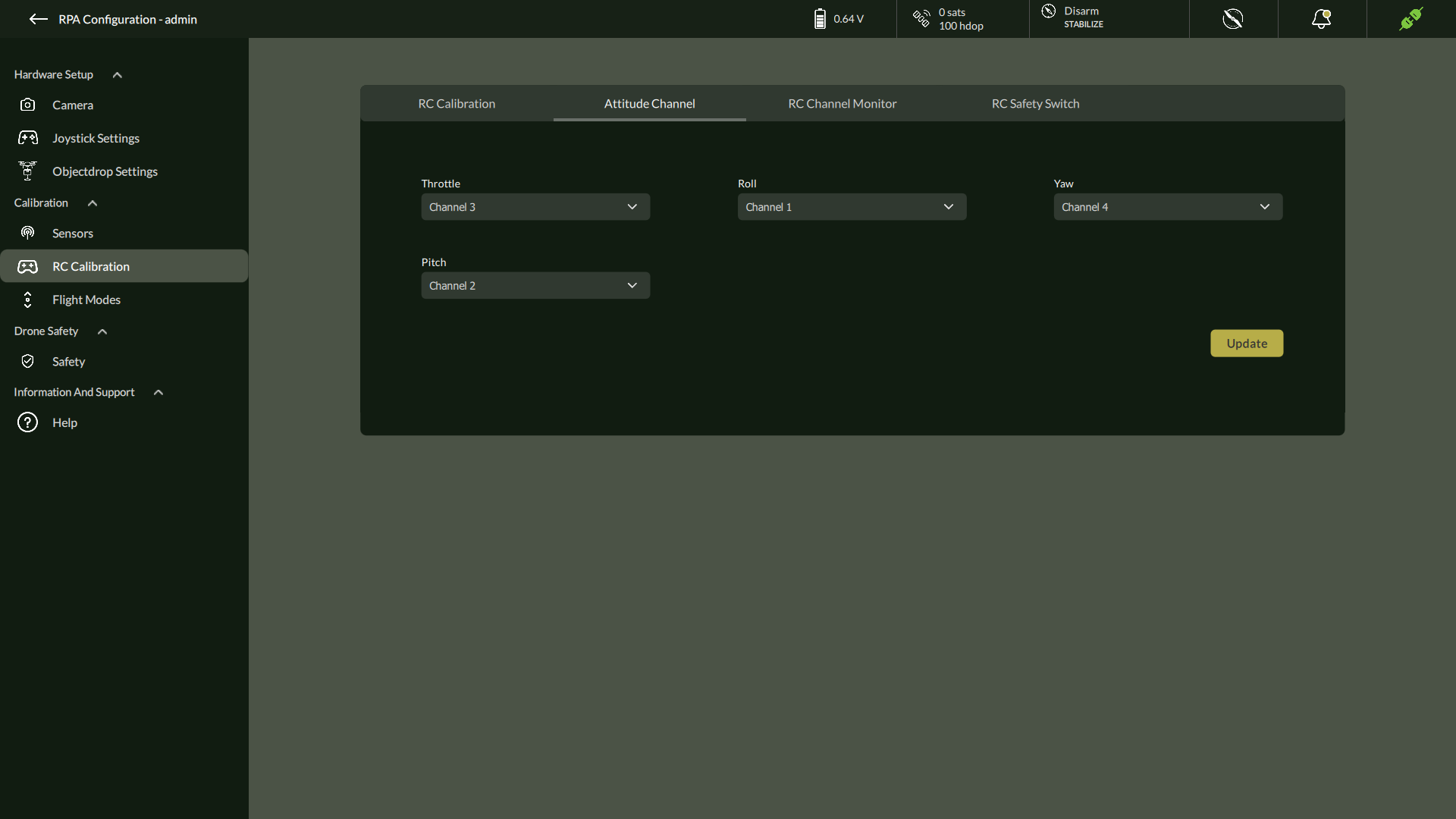
F. RC Calibration
- Go to Settings > Calibration > RC Calibration
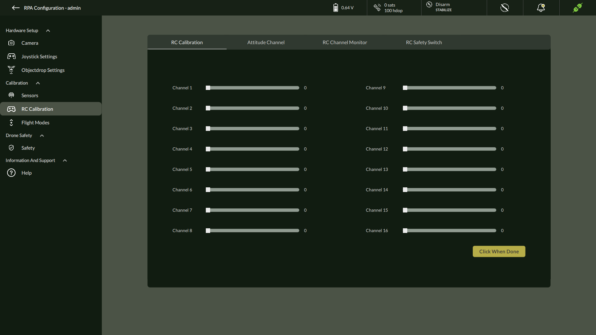
2. Click Calibrate
3. Move all RC sticks as instructed
4. Confirm when done
5. Set channel mappings for Throttle, Roll, Pitch, Yaw
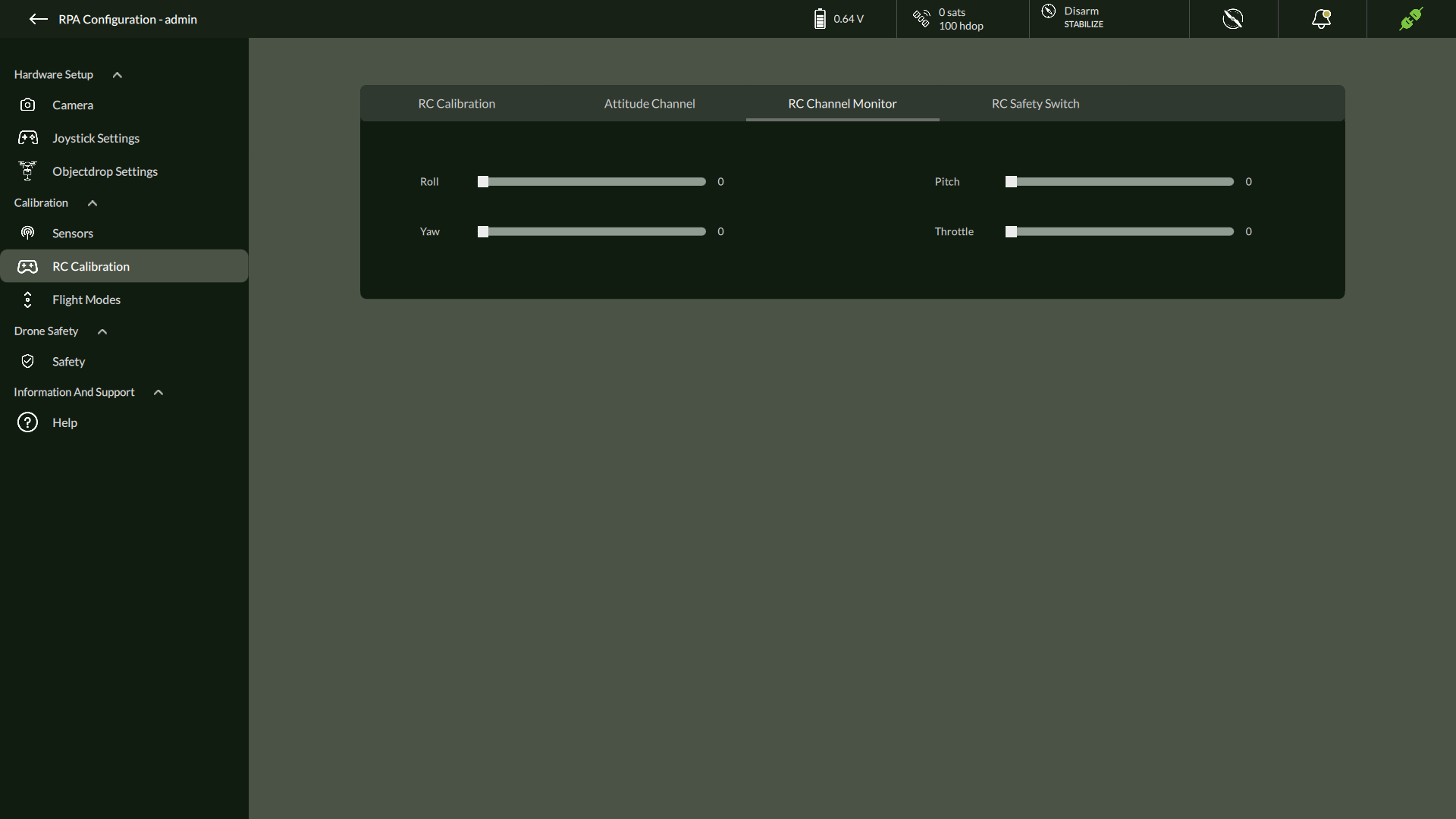
6. Monitor RC Channel
7. Enable / Disable RC Safety Switch
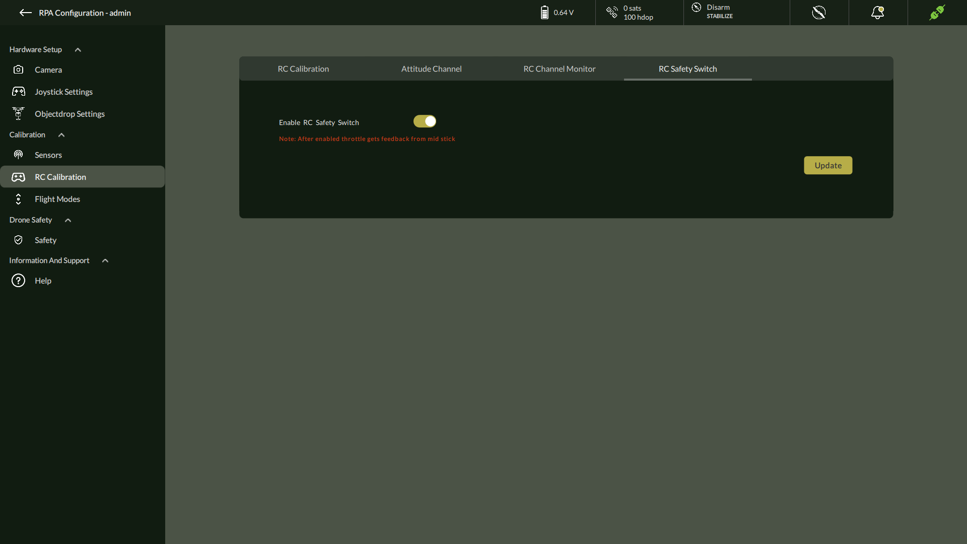
8. Click Update
9. This will confirm by showing message dialog “Parameter Sent to Device”.
10. Click “Ok” to continue.
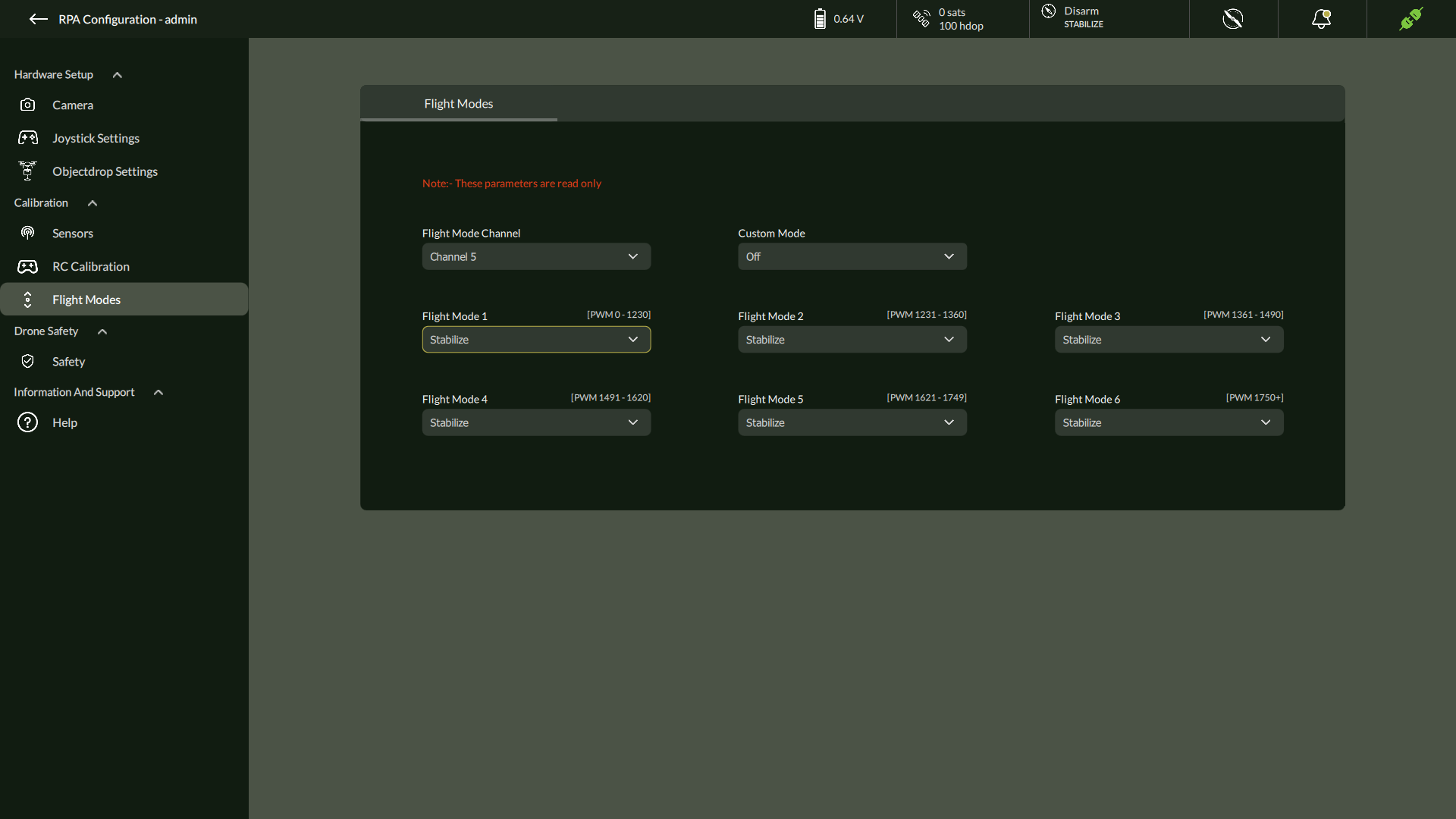
G. Flight Modes (Read-Only)
Displays OEM-defined flight modes and channel mappings.
| Parameter | Description |
| Mode 1 – Mode 6 | Preset flight behaviors |
| Flight Mode Channel | RC channel for switching modes |
| Custom Mode Value | OEM-defined logic |
5.6.3 Drone Safety

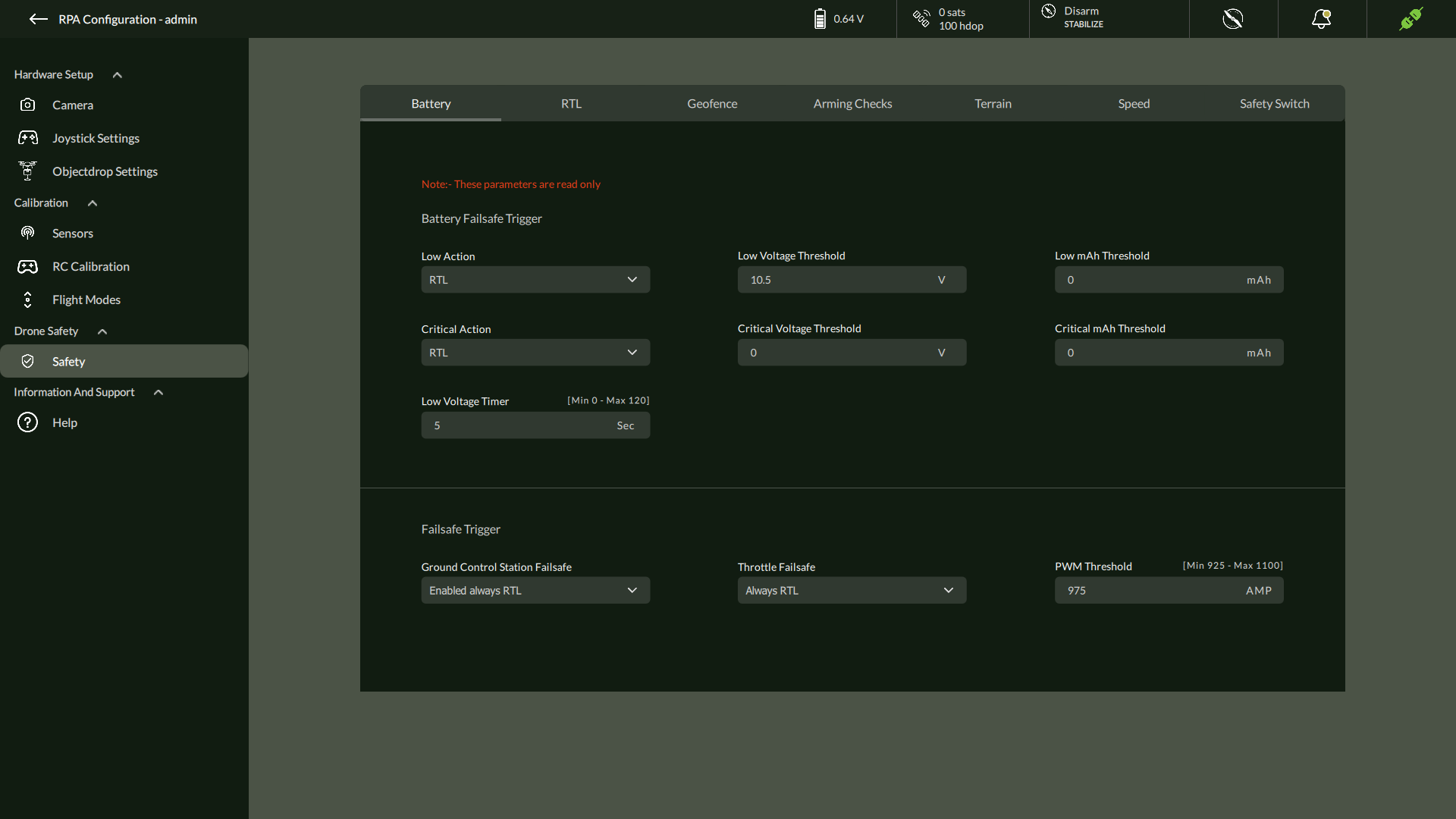
A. Battery Settings (View Only)
Displays critical battery thresholds and actions.
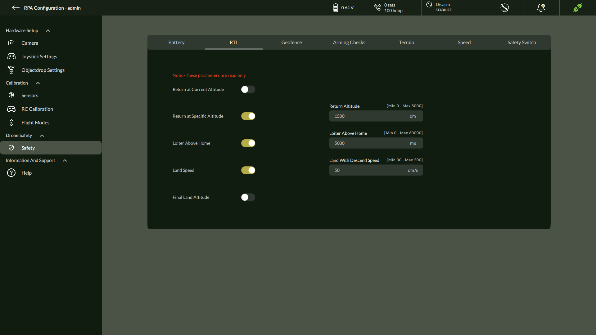
B. Return to Launch (RTL) (Read Only)
Configured RTL altitude, loiter, and landing speed.
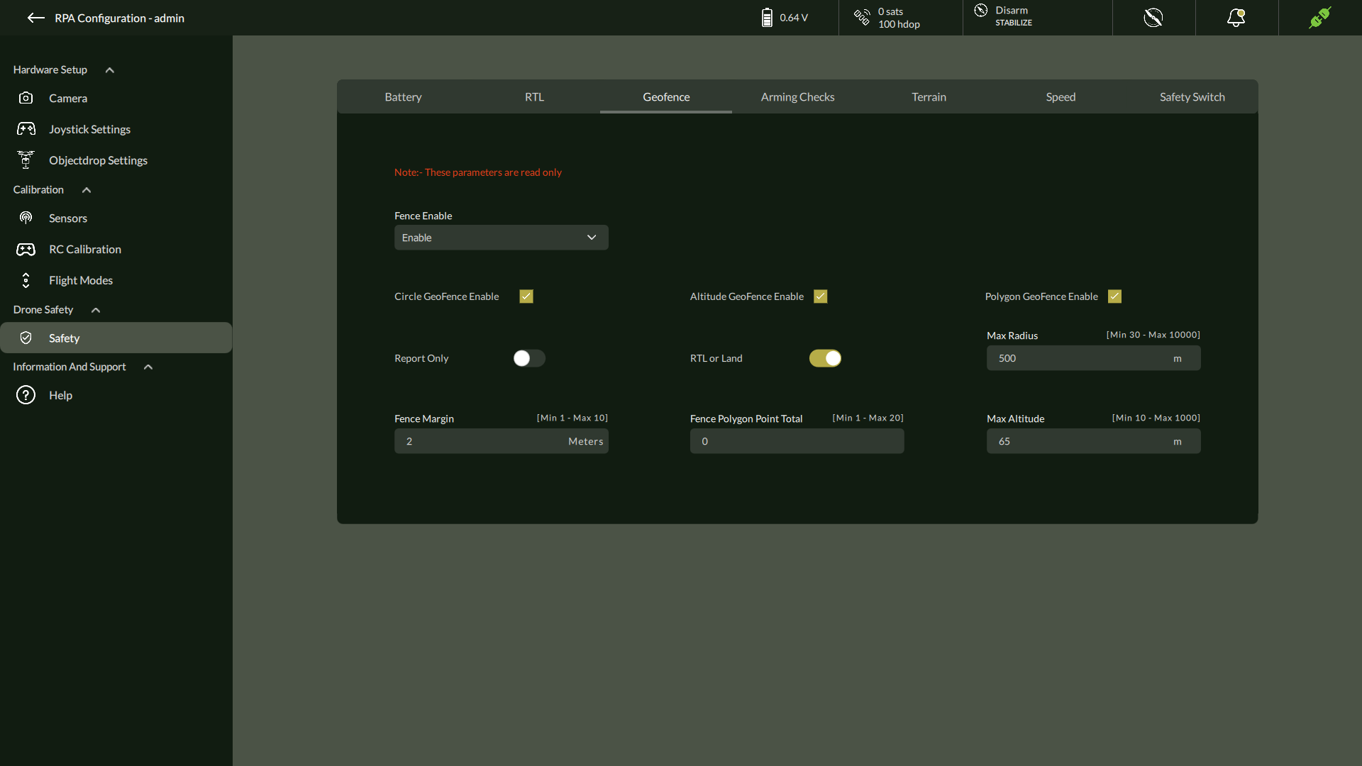
C. Geofence Settings (Read Only)
Predefined boundaries configured to restrict the flight zone.
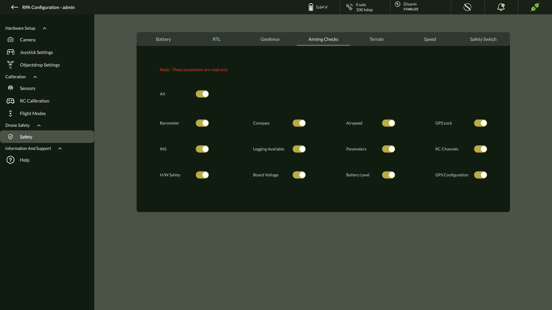
D. Arming Checks (Read Only)
Display of all mandatory arming pre-checks.
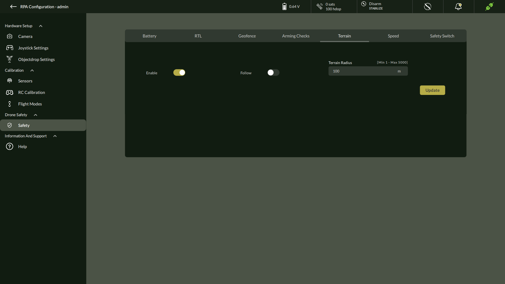
E. Terrain Settings
Configure whether the drone follows terrain elevation.
- Toggle Enable and Follow
- Set Terrain Radius
- Click Update
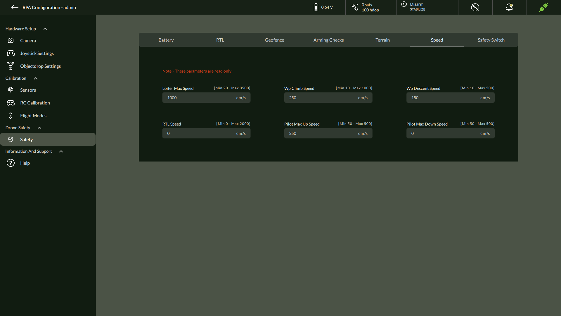
F. Speed
Speed Configuration
The Speed tab under Drone Safety settings provides a view of critical velocity parameters associated with drone movement and flight safety. These parameters are read-only and displayed in centimeters per second (cm/s). They allow users to monitor the predefined speed limits for various operations.
| Parameter | Description | Range |
| Loiter Max Speed | Maximum allowed speed while loitering | [Min 20 – Max 3500] cm/s |
| WP Climb Speed | Speed at which the drone climbs to waypoint altitudes | [Min 10 – Max 1000] cm/s |
| WP Descent Speed | Speed at which the drone descends to waypoint altitudes | [Min 10 – Max 500] cm/s |
| RTL Speed | Speed during Return to Launch (RTL) mode | [Min 0 – Max 2000] cm/s |
| Pilot Max Up Speed | Maximum manual ascent speed | [Min 50 – Max 500] cm/s |
| Pilot Max Down Speed | Maximum manual descent speed | [Min 50 – Max 500] cm/s |
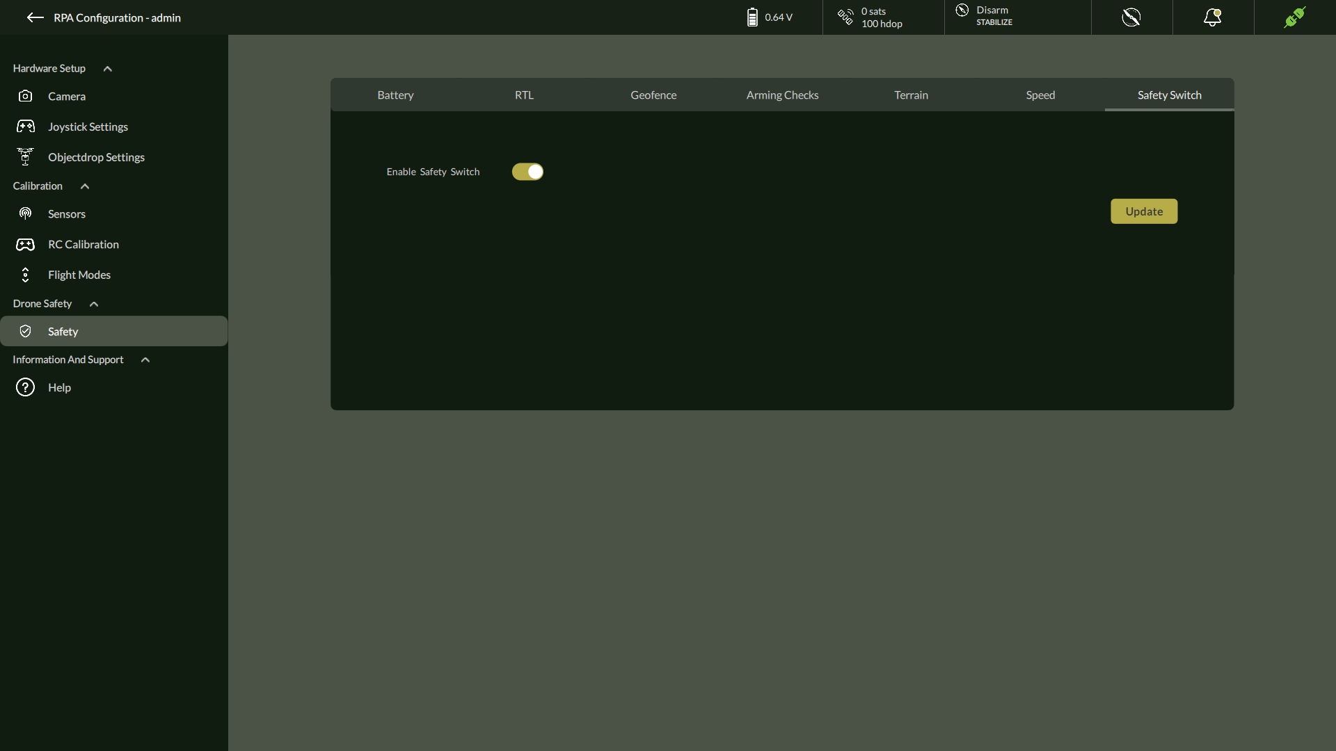
G. Safety Switch
An additional setting in AeroGCS DEFENCE to enable/disable an onboard safety switch.
| Parameter | Description | Option |
| Added Safety Switch | Hardware-level flight protection | Enable/Disable |
✅ Summary & Best Practices
- Calibrate all sensors before each mission.
- Use Relay/Servo modes as per camera specs.
- Always review failsafe settings before launch.
- Enable the Safety Switch to ensure mission integrity.
5.7. Motor Test
The Motor Test feature in AeroGCS DEFENCE allows users to verify the functionality of individual motors before flight. It is designed to support pre-flight inspection and hardware diagnostics while ensuring operator safety and mission readiness.
Accessing Motor Test
To access the Motor Test feature:
- Connect the drone to AeroGCS DEFENCE.
The Motor Test option becomes available only when the drone is connected.
- On the top navigation bar, locate the Motor Test icon
(positioned just before the notification bell icon). - Click the Motor Test icon to open the motor testing interface.
Performing the Motor Test
Once the Motor Test panel opens:
- Each motor can be individually tested to verify its operational status.
- The test activates each motor one at a time in a controlled sequence.
- The interface displays real-time feedback during motor activation.
Important Safety Instructions
- The drone must be disarmed to initiate the motor test.
- Motor test cannot be performed when the drone is armed.
- Ensure the drone is on a flat, stable surface.
- It is recommended to remove the propellers before testing, following standard operating procedures (SOPs).
This feature is strictly intended for maintenance and diagnostic purposes. Use it with caution, adhering to safety protocols at all times.
5.8. Information & Support
The Information & Support panel is the fourth tab available under the Settings screen in AeroGCS DEFENCE. This section provides built-in help resources, including access to the official online user manual and an FAQ (Frequently Asked Questions) repository to assist with usage, configuration, and troubleshooting.
Navigation Path:
From the Home screen, click the three-dot menu in the top-right corner → Select Settings → Navigate to the Information & Support tab.
Overview of Tabs
The Information & Support section includes two tabs:
- User Manual
- FAQs
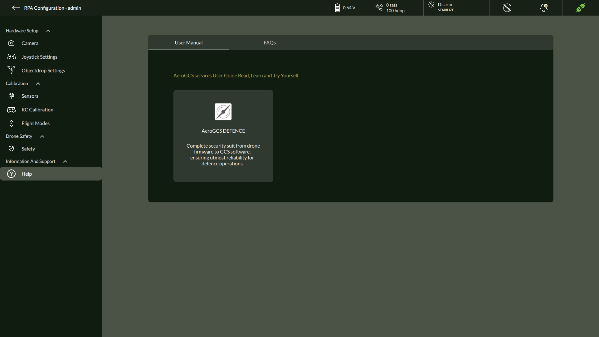
A. User Manual
The User Manual tab offers a shortcut to the AeroGCS DEFENCE Online User Manual hosted on the web. It contains detailed documentation on:
- Software features
- Step-by-step configuration workflows
- Safety procedures and mission best practices
How to Access:
- Click on the AeroGCS DEFENCE tile within the User Manual tab.
- The system will open the latest version of the documentation in your default web browser.
💡 Ensure an active internet connection to view the online documentation.
B. FAQs (Frequently Asked Questions)
The FAQs tab contains searchable solutions to common user queries related to drone operations, calibration, safety configuration, and troubleshooting.
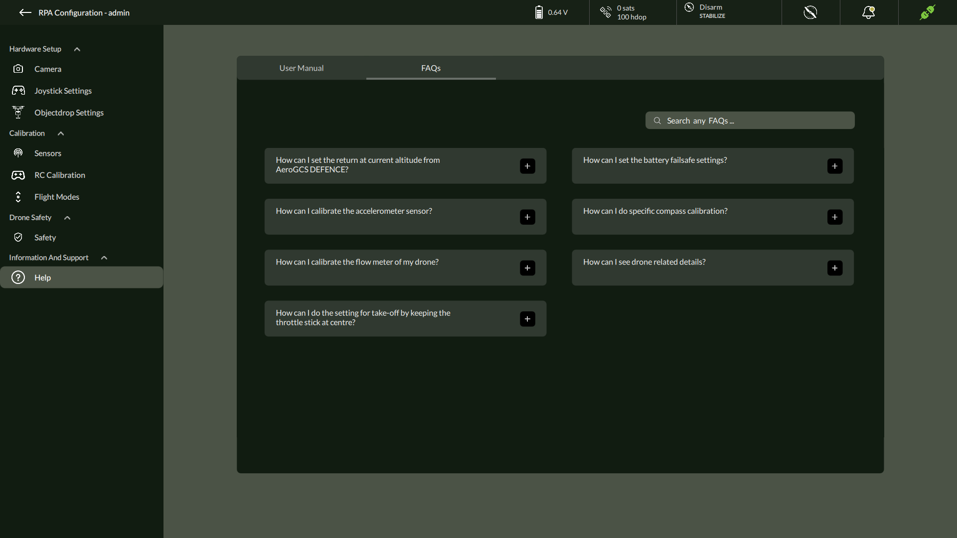
Topics Commonly Covered:
- How to calibrate the accelerometer or compass
- Setting battery failsafe thresholds
- Understanding RC channel mappings
- Configuring flow meter correction values
- Adjusting RTL parameters
- Safety and geofencing overview
Use the search bar to filter FAQs by topic or keyword.
Action Table – Quick Reference
| Action | Description |
| Access Settings | Home screen → Three-dot menu → Settings |
| Open Help Section | Click the Information & Support tab |
| View Online Manual | Click AeroGCS DEFENCE tile in the User Manual tab |
| Browse FAQs | Go to FAQs tab and use the search bar |
| Internet Requirement | Required for accessing online manual and FAQ updates |
Best Practices
✔️ Bookmark the online manual in your browser for frequent reference.
✔️ Review FAQs before contacting support—it often contains direct solutions.
✔️ After software updates, revisit the manual for new feature documentation.
5.9. About and Exit
About
The About option provides key versioning and copyright information related to the AeroGCS DEFENCE software.
To access:
- Click the three-dot menu in the top-right corner of the Flight View screen.
- Select About from the dropdown.
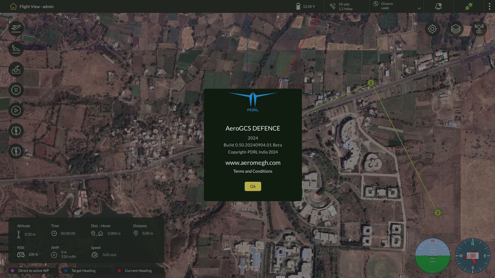
The dialog displays:
- Software Name: AeroGCS DEFENCE
- Release Year: 2024
- Build Information: Example – Build 0.50.20240904.01 Beta
- Copyright: PDRL India 2024
- Website: aeromegh.com
- Terms and Conditions: Clickable link if available
Click OK to close the About window and return to the application.
Exit
To exit the application:
- Open the three-dot menu from the top-right corner.
- Click Exit.
The application will close immediately without saving any unsaved mission data or logs.
| ⚠️ Note: Always ensure mission execution is completed and logs are saved before exiting the software. |