-
AeroGCS Enterprise User Manual
8. Projects
Organise, Assign, and Monitor Drone Missions with Centralised Project Management
8.1 Introduction
The Projects module in AeroGCS Enterprise provides a centralised workspace for managing all drone-based operations within your organisation. Each project acts as a structured container that groups together related flight plans, pilots, drones, telemetry data, and performance metrics.
Whether you’re managing a single farm, coordinating a regional survey, or monitoring multiple ongoing missions, the Projects module enables streamlined execution, improved traceability, and real-time visibility across your operations.
When you access this module, you will see a unified list of projects associated with your organisation, including:
- Projects created directly within AeroGCS Enterprise
- Projects synchronised automatically from AeroGCS applications, such as AeroGCS GREEN, AeroGCS ORANGE, and other supported ground control systems
This synchronisation ensures seamless data continuity between your field operations and enterprise-level command centre—without the need for manual uploads or data transfer.
With the Projects module, you can:
- Create and manage drone operation projects tailored to specific missions or locations
- Assign pilots and link flight plans for operational readiness
- Monitor mission outcomes, telemetry, and flight history in a central dashboard
- Access flight replays and mission analytics for review or auditing
💡 Tip: Defining your drone operations into project-specific containers improves oversight, enhances collaboration, and enables precise reporting.
Project Synchronization Across AeroGCS Software
Projects, plans, and plots created in AeroGCS Enterprise are automatically synchronised with compatible AeroGCS desktop and field applications (such as AeroGCS GREEN, AeroGCS ORANGE, etc.) when:
- The user is logged in to the software with the same registered credentials
- The Enterprise section is logged into AeroGCS Enterprise
- Sync is performed either automatically or manually via the sync option
This ensures that project configurations created in the web application are always available for mission execution from AeroGCS software in the field or control room.
💡 Tip: Maintain stable internet access and verify login status for successful synchronisation.
8.2 Accessing the Projects Page
To begin managing projects in AeroGCS Enterprise, you must first open the Projects module from the main application interface.
Steps to Access the Projects Page:
- Log in to the AeroGCS Enterprise web portal using your registered credentials.
- From the left-hand navigation panel, locate and click on the “Projects” menu option.
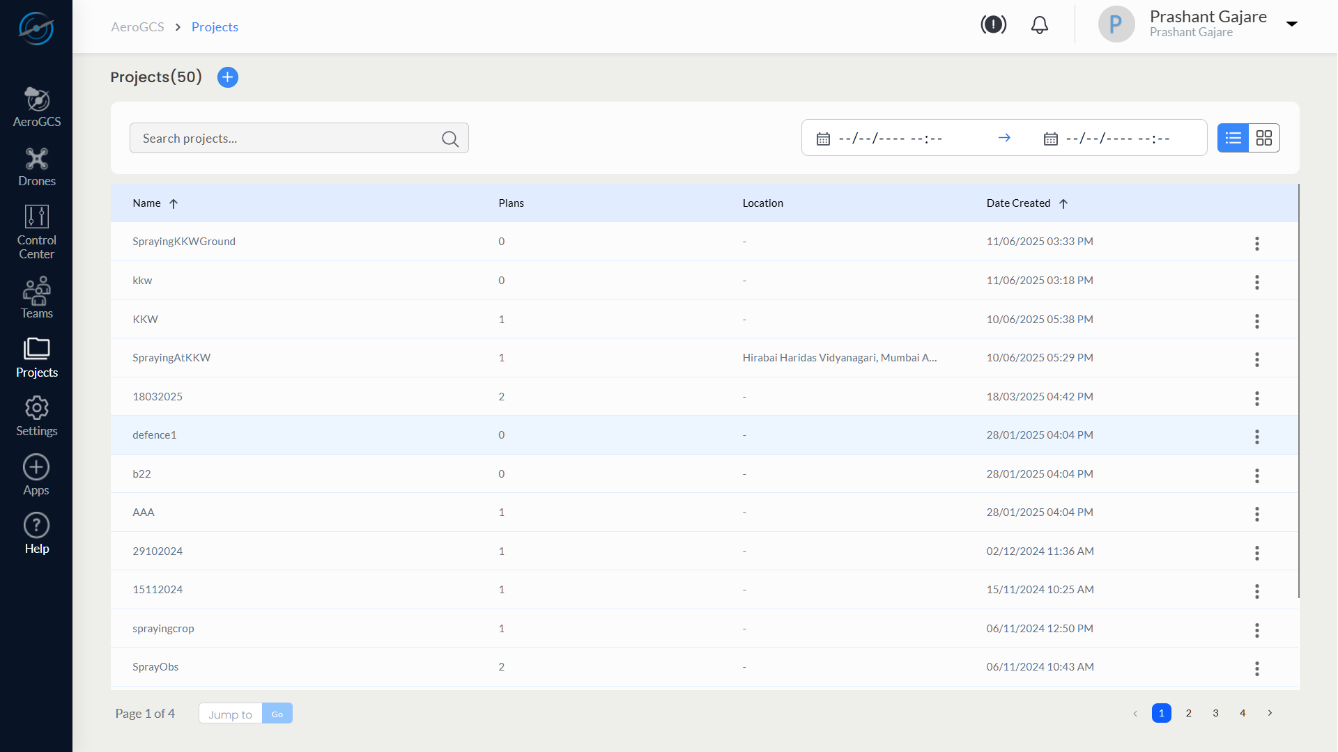
- The Projects List View will open, displaying all available projects, including:
– Projects manually created within the Enterprise platform
– Projects synchronised from AeroGCS GREEN, AeroGCS ORANGE, or other integrated AeroGCS applications
8.3 Creating a New Project
Define, Assign, and Configure Drone Missions in AeroGCS Enterprise
The Create Project workflow in AeroGCS Enterprise allows you to set a mission location, optionally assign a drone, define operational parameters, draw a boundary, and generate an optimised flight plan. This guided, map-based interface ensures efficient and safe drone mission planning for agricultural, surveying, and waypoint-based operations.
Steps to Create a New Project
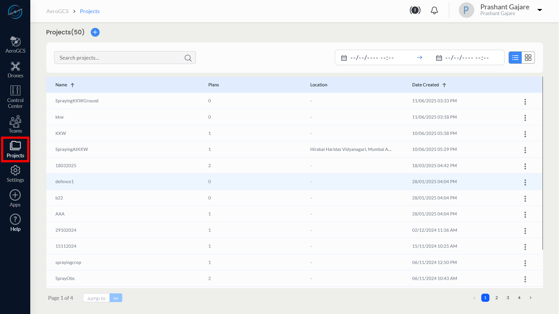
Step 1: Access the Projects Module
- Click the Projects tab from the left-hand sidebar to open the Projects dashboard.
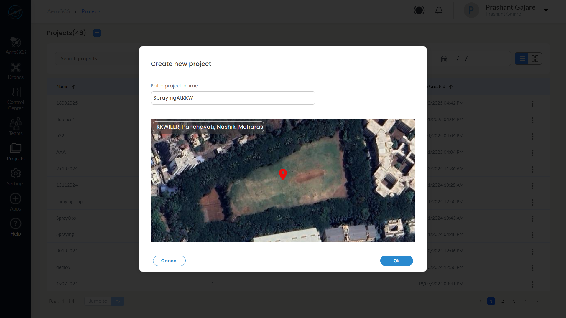
Step 2: Create Project
- Click the Create New Project button on the Projects screen.
- A modal window appears with:
– Enter Project Name field
– Map preview of the current/default location - Enter a suitable Project Name .
- Confirm the map pin location.
- Click OK to proceed.
💡 Tip: Use descriptive naming conventions (site + mission type) for traceability.
Step 3: Select Location and Drone
- The system loads the Flight Plan map view.
- Use the map search or navigation controls to position the marker on your desired mission area.
- Click on the map to mark the precise location.
- From the Select Drone dropdown, choose a compatible drone if one is available for that location (e.g., AeroGCS GREEN).
- If no drone is currently assigned to the selected area, you may continue without drone selection and assign it later.
- Click the Next button to continue.

Note: Drone selection is optional at this stage. If no drone is available for the selected location, you may still proceed with mission planning and assign a drone before execution.
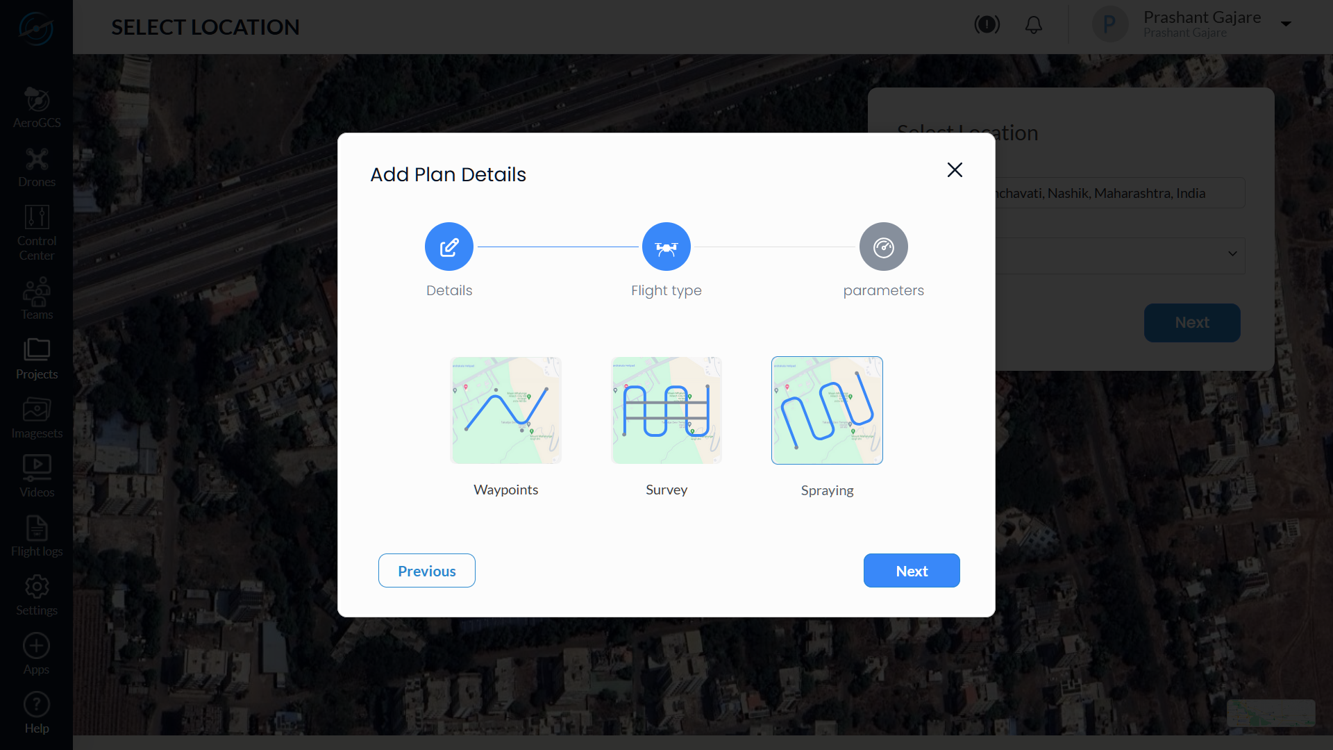
Step 4: Add Plan Details
The Add Plan Details form is presented in a 3-step wizard format.
4.1 Enter Project and Plan Name
- The Project Name is pre-filled (editable).
- Enter a Plan Name (e.g., SprayMission1).
- Click Next.

4.2 Select Flight Type
- Choose your desired Flight Type:
– Waypoints
– Survey
– Spraying - Click Next to proceed.
💡 Tip: Use Spraying for precision agriculture and chemical application.
4.3 Enter Flight Parameters
- Enter the required Altitude in metres (range: 1–121 m).
- Enter the Flight Speed in m/s (range: 1–20 m/s).
- Click Next to proceed to boundary marking.
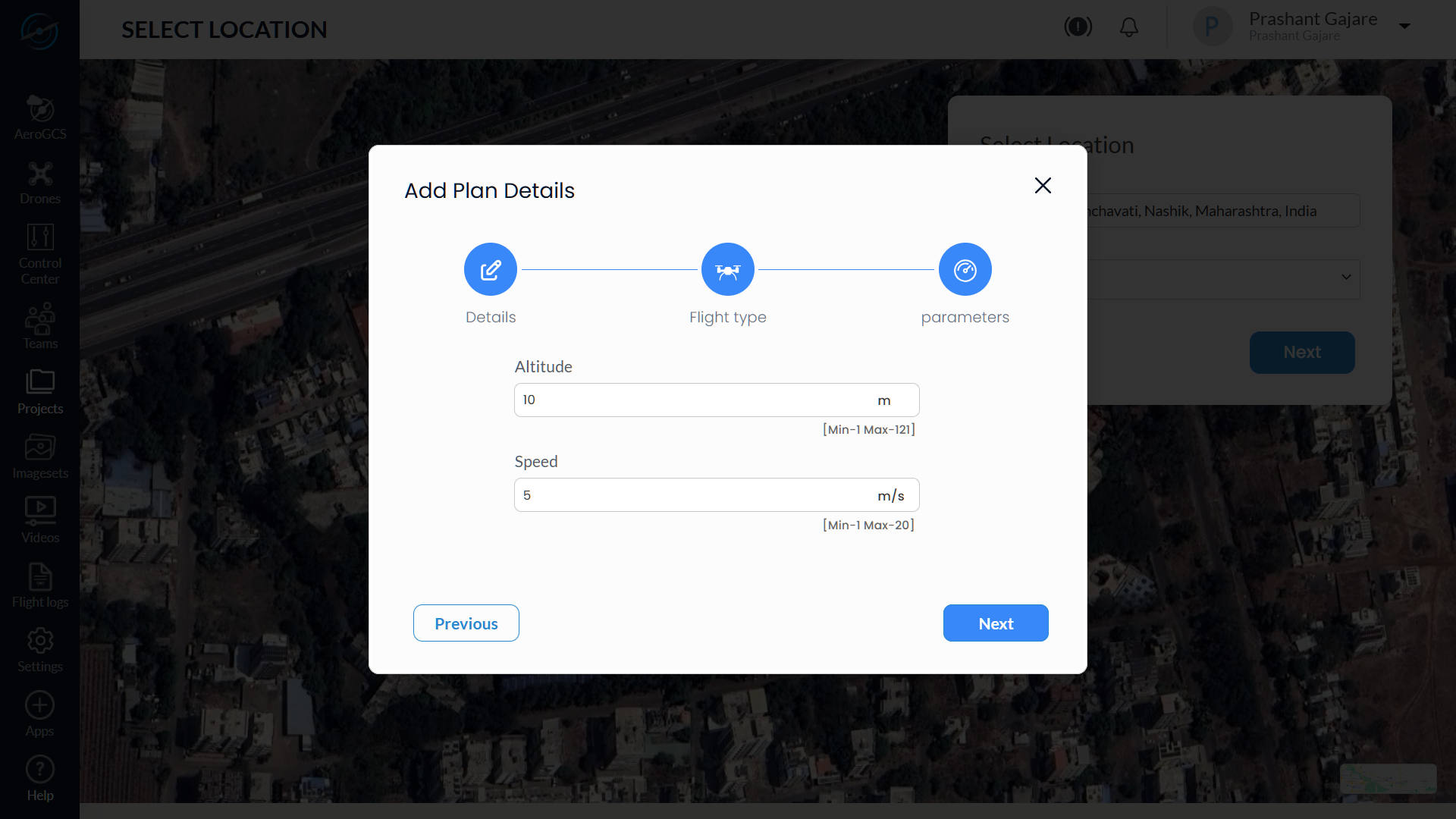
⚠️ Warning: Ensure parameters comply with drone specs and safety regulations.
Step 5: Create Plot and Define Boundaries
5.1 Create Plot Boundary
- The system now enters plot drawing mode automatically.
- Click on the map to mark boundary points around the target area.
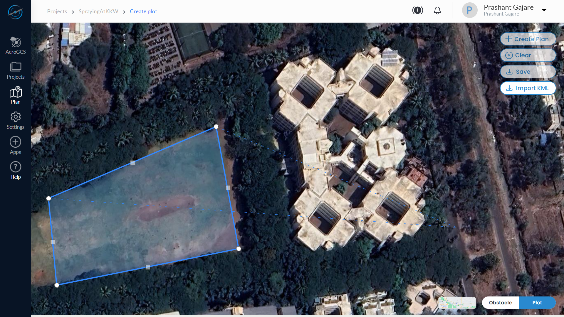
3. After placing all required points, click again on the last point to close and finalise the polygon.
4. The enclosed area is recognised as the Fence Boundary.
5. If needed, click the Clear button on the map to remove all points and start again.

💡 Tip: Add at least three points to form a valid polygon. Use satellite view for better accuracy.
5.2 Add Obstacles (Optional)
After completing the plot boundary, you can mark internal no-fly zones such as trees, ponds, electric poles, or structures using the Obstacle Tools.
Steps to Add Obstacles
- Use the toggle buttons located at the bottom-right corner of the screen to switch from Plot mode to Obstacle mode.
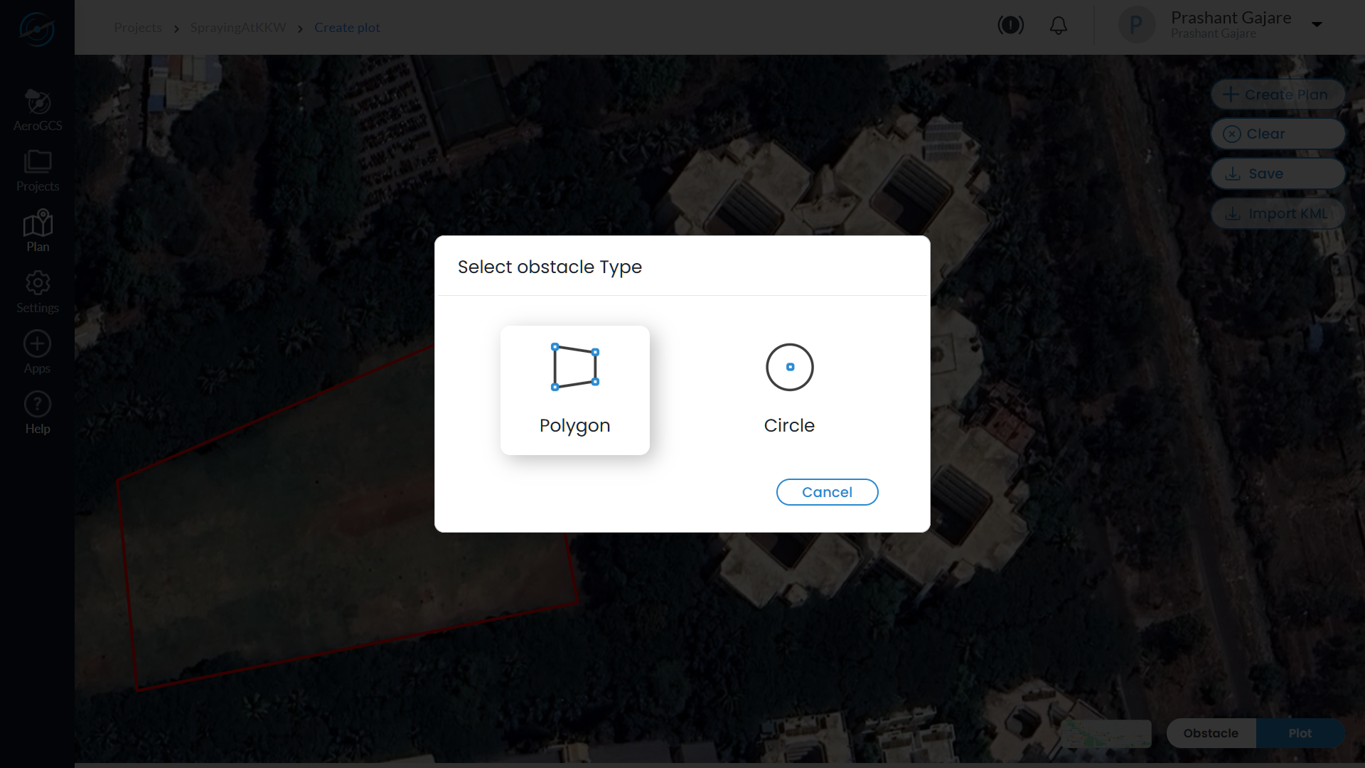
- Click the Obstacle Tool from the toolbar on the map interface.
- Choose the desired shape for your obstacle area:
- Polygon Tool – for custom or irregular-shaped obstacles
- Circle Tool – for round objects like tanks, trees, or wells
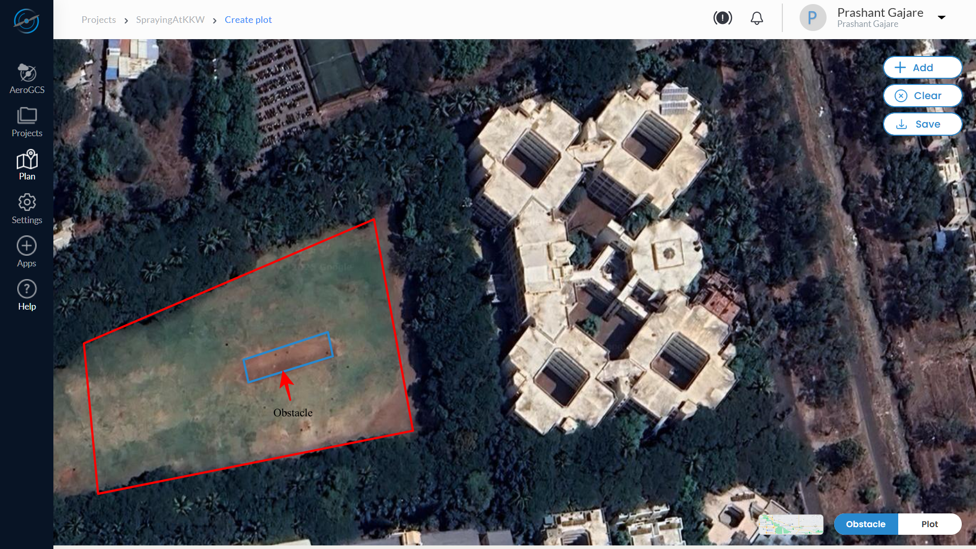
To Draw a Polygon Obstacle
- Select the Polygon Tool.
- Click on the map to mark the first point of the obstacle.
- Continue clicking to define each corner point of the polygon.
- After placing the final point, click on the final point again to close and complete the shape.
- The defined zone will now be treated as an obstacle and excluded from the flight path.
💡 Tip: Use polygon obstacles for irregular layouts like buildings, fenced structures, or terrain anomalies.
To Draw a Circle Obstacle
- Select the Circle Tool.
- Click once on the centre point of the obstacle (e.g., centre of a tree).
- Move the cursor outward and click again to define the radius of the obstacle.
- The circle is drawn and automatically registered as a no-fly zone.
💡 Tip: Use circle obstacles for consistent shapes such as water tanks, single trees, or poles.
⚠️ Warning: Obstacles not marked during planning may result in unsafe flight paths or mission failure.
💡 Tip: Obstacle zones help auto-route safe paths around obstructions.
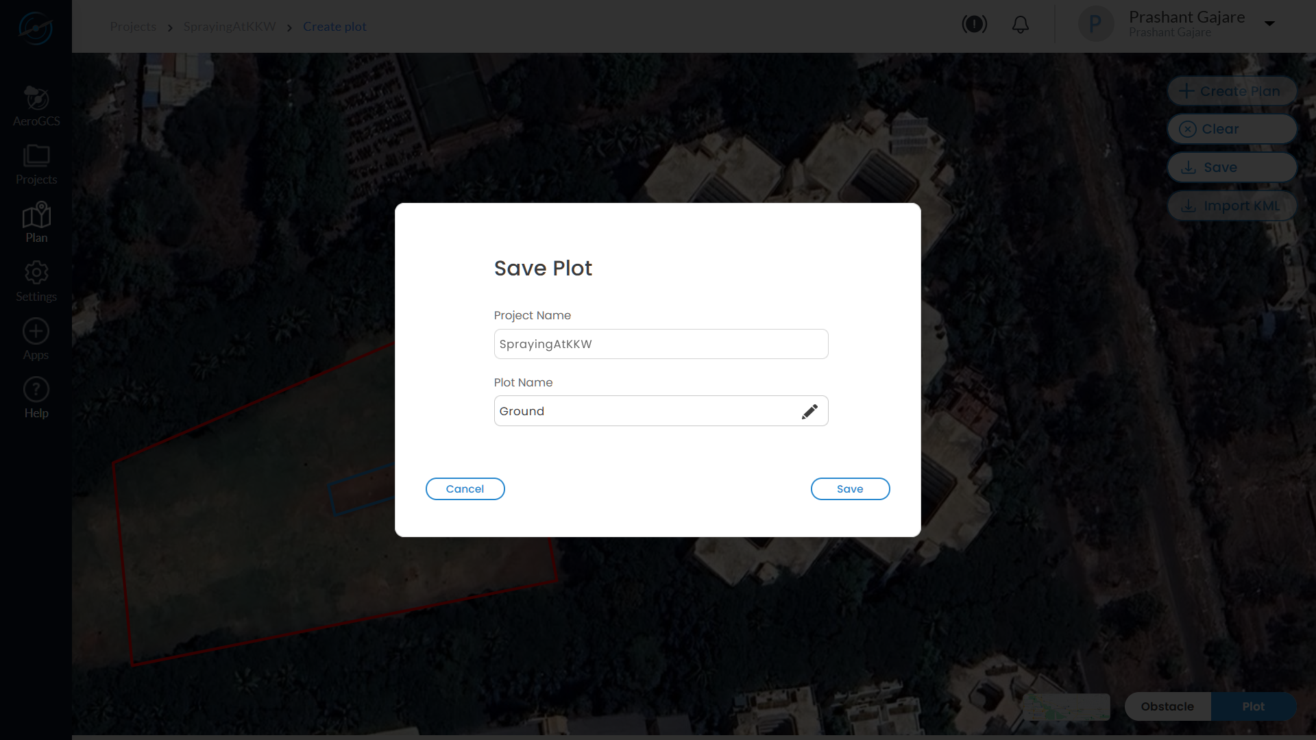
5.3 Save the Plot
- Once boundaries and obstacles are marked, click Save Plot.
- Confirm or adjust the Project Name and Plot Name if prompted.
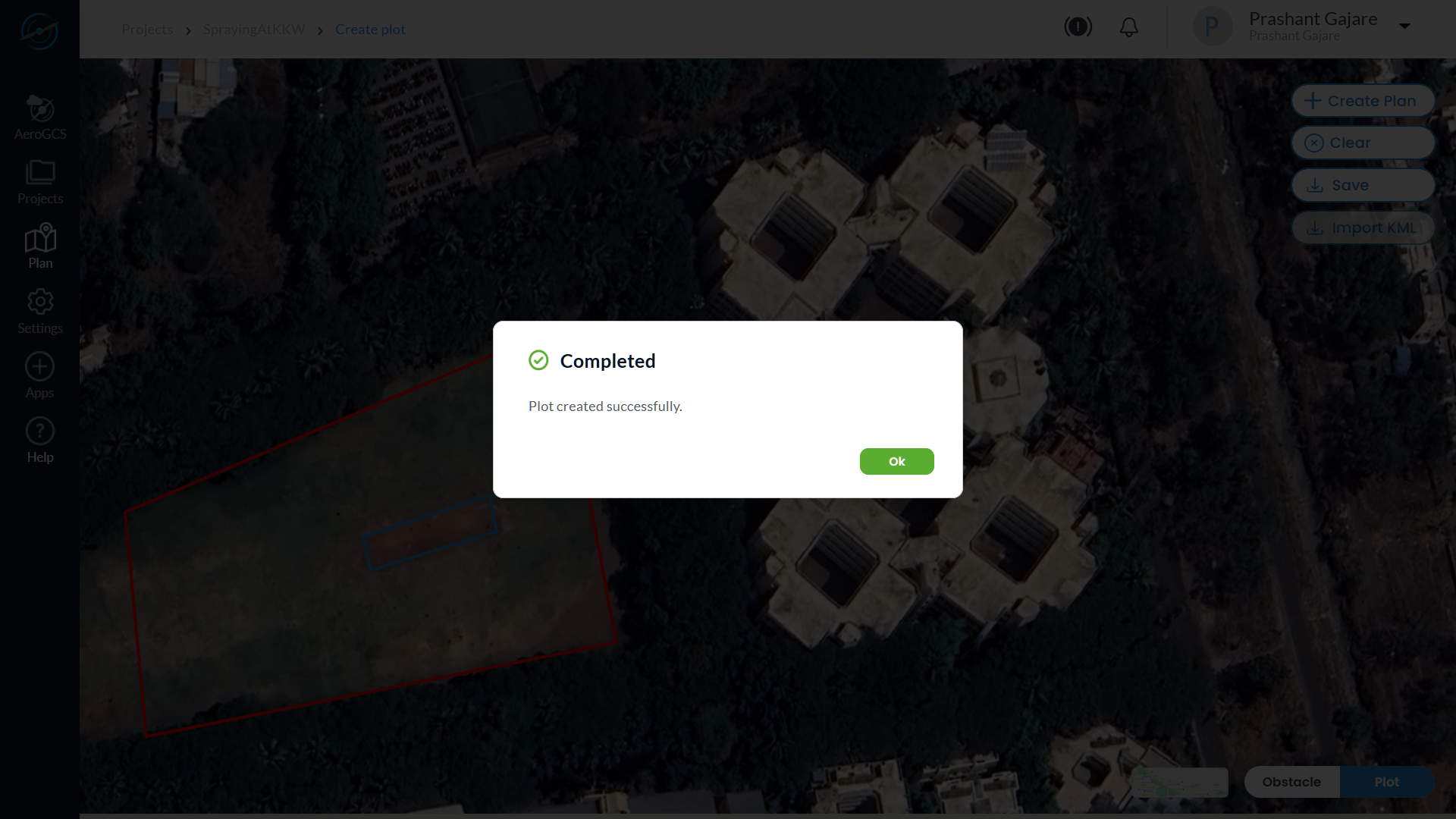
3. A message “Plot Created” confirms success.
5.4 Create Plan for the Defined Plot
- Once the plot is saved, click the + Create Plan button visible on the screen.

2. This action initiates flight plan generation based on the previously defined plot and selected plan type.
3. The system now transitions to the Flight Plan Configuration screen, where a default grid-based path is generated.

💡 Tip: This step is required to move from plot definition to flight path configuration.
Step 6: View and Configure Flight Plan
After saving the plot, AeroGCS Enterprise generates a default flight path which can be fine-tuned using the Tools dropdown.
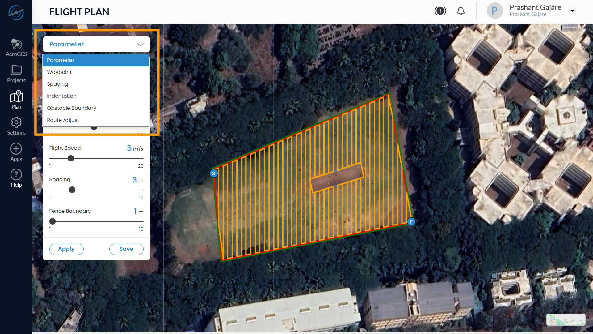
6.1 Configure Path Using Tools
After defining the plot and saving it, a default flight plan grid is auto-generated. You can now refine the route using the Tools dropdown, located in the top-left corner of the map interface.
Available Tools and Their Functions
Tool | Function |
Waypoint | Move the entire grid using directional arrows |
Spacing | Adjust spacing between flight lines for coverage control |
Indentation | Add margin between fence boundary and the start of flight lines |
Obstacle Boundary | Set a safe distance between the flight path and obstacle zones |
Route Adjust | Rotate the entire flight grid by a defined angle |
Parameter | Update altitude, speed, spray rate, and other mission variables |
Step-by-Step Usage for Each Tool
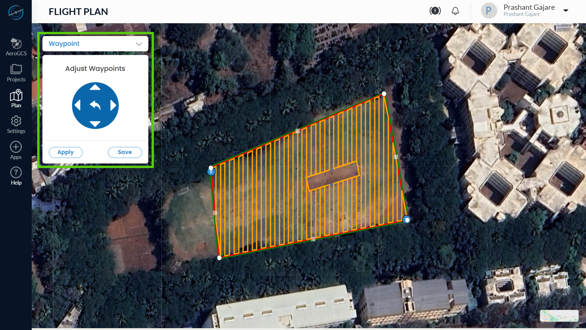
Waypoint Tool
The Waypoint Tool allows you to adjust individual waypoints by selecting, dragging, or shifting them using the Waypoint Adjustment Control. This is useful for making precise changes without redrawing the entire flight plan.
Steps to Use the Waypoint Tool:
- From the Tools dropdown in the top-left of the map, select Waypoint.
- The Waypoint Adjustment Tool appears on the screen, displaying:
- Four directional arrows (↑ ↓ ← →) to shift the selected waypoint
- A centre arrow to revert the waypoint to its original position
- Apply and Save buttons
3. Click anywhere inside the flight grid to enable the display of waypoints.
4. To edit a waypoint:
- Right-click on the desired waypoint to select it.
- The waypoint will highlight, indicating it is ready for adjustment.
5. Now choose one of the following actions:
- Use the directional arrows to shift the waypoint incrementally.
- Click and drag the selected waypoint directly on the map to reposition it manually.
6. To revert the waypoint to its original position, click the centre arrow on the control panel.
7. To delete a waypoint, left-click on it after it is selected.
8. After adjusting, click Apply to preview the changes.
9. Click Save to finalise the adjustments and update the plan.
💡 Tip: Use dragging for quick visual repositioning and arrows for precise alignment.
⚠️ Warning: Avoid moving or deleting edge waypoints unless necessary, as it may affect flight pattern integrity.
Spacing Tool
The Spacing Tool allows you to control the distance between consecutive flight lines (rows) in the grid. This is useful for optimising coverage depending on terrain type, spray width, or camera overlap requirements.
Steps to Use the Spacing Tool:
- Select Spacing from the Tools dropdown on the map interface.
- The Adjust Spacing panel appears, showing:
- A diagram with green vertical lines representing the spacing rows
- A slider bar and + / – buttons to modify the spacing value
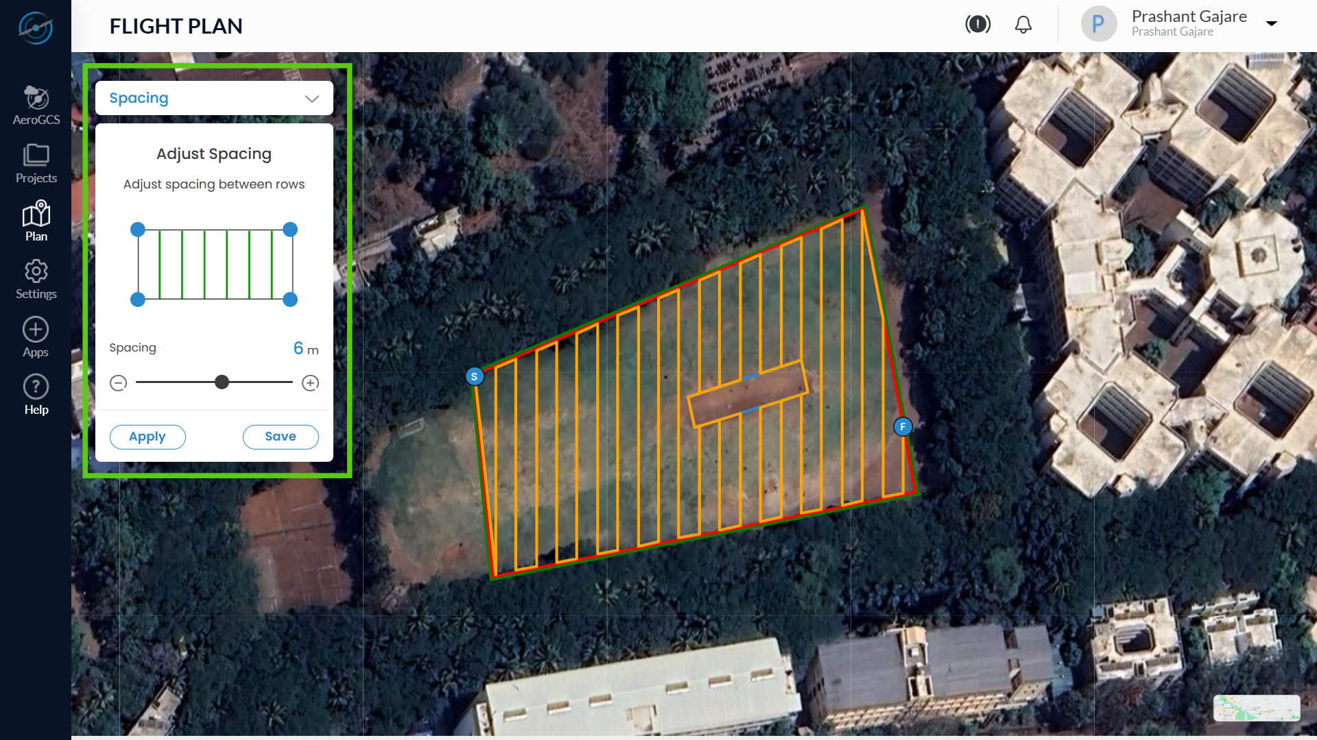
3. Use the + button to increase spacing, or the – button to reduce it.
- You can also move the slider knob left or right to set the desired spacing value (e.g., 3 m, 6 m, etc.).
4. Click Apply to preview how the updated spacing affects the grid layout on the map.
5. Click Save to confirm and finalise the new spacing configuration.
💡 Tip: Wider spacing reduces flight time but may leave coverage gaps. Narrower spacing increases overlap but may consume more battery and time.
⚠️ Note: Always check field and payload type before setting final spacing values.
Indentation Tool
The Indentation Tool allows you to adjust the internal margin between the plot boundary and the start of the flight path. This creates a safe buffer zone, ensuring the drone does not fly too close to field edges.
Steps to Use the Indentation Tool:
- From the Tools dropdown, select Indentation.
- The Adjust Indentation panel appears with:
- A visual diagram representing flight lines and buffer zones
- A slider to control indentation distance
- + / – buttons to increment or reduce the margin (e.g., 4 m)
- Left ( < ) and Right ( > ) arrow controls to cycle through different boundary edges
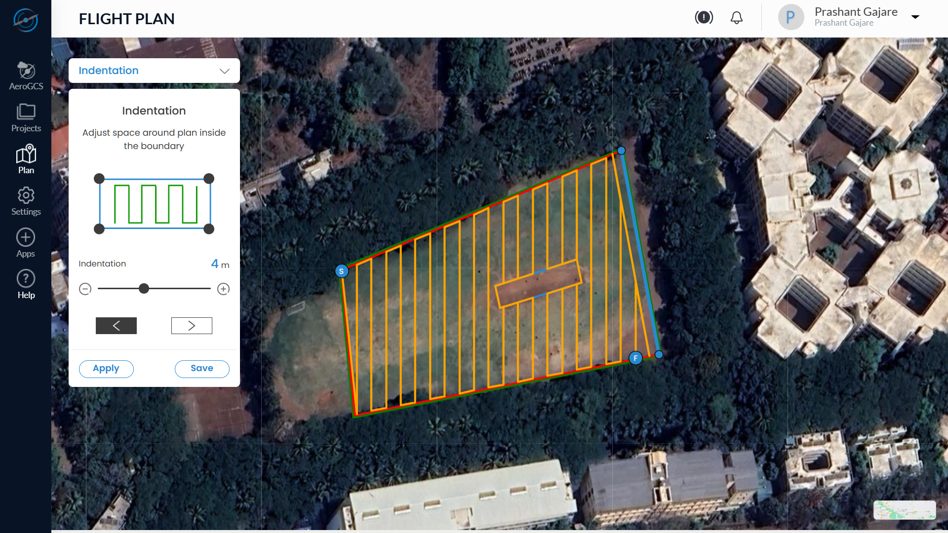
3. By default, the first edge of the boundary is selected for indentation adjustment.
4. To adjust the buffer on the selected edge:
- Use the + button to increase spacing
- Use the – button to decrease spacing
- Or slide the control to set a custom value
5. To apply indentation to a different edge:
- Click the > button to move to the next edge
- Click the < button to return to the previous edge
6. After adjustments:
- Click Apply to preview the changes on the grid
- Click Save to finalise and store the indentation settings
💡 Tip: Use indentation to avoid fence collisions, especially near trees, roads, or buildings bordering the plot.
⚠️ Note: Adjusting indentation per edge allows granular control over drone flight behaviour around irregular-shaped fields.
Obstacle Boundary Tool
The Obstacle Boundary Tool allows you to set a safety buffer between the flight path and any defined obstacles (e.g., trees, structures, water tanks) within the plot. This ensures that drones do not fly too close to restricted or hazardous zones.
Steps to Use the Obstacle Boundary Tool:
1. Select Obstacle Boundary from the Tools dropdown.
2. The Obstacle Boundary panel opens, displaying:
- A visual diagram representing the obstacle and buffer zone
- A slider control for distance adjustment
- + / – buttons to fine-tune the spacing value (e.g., 2 m)
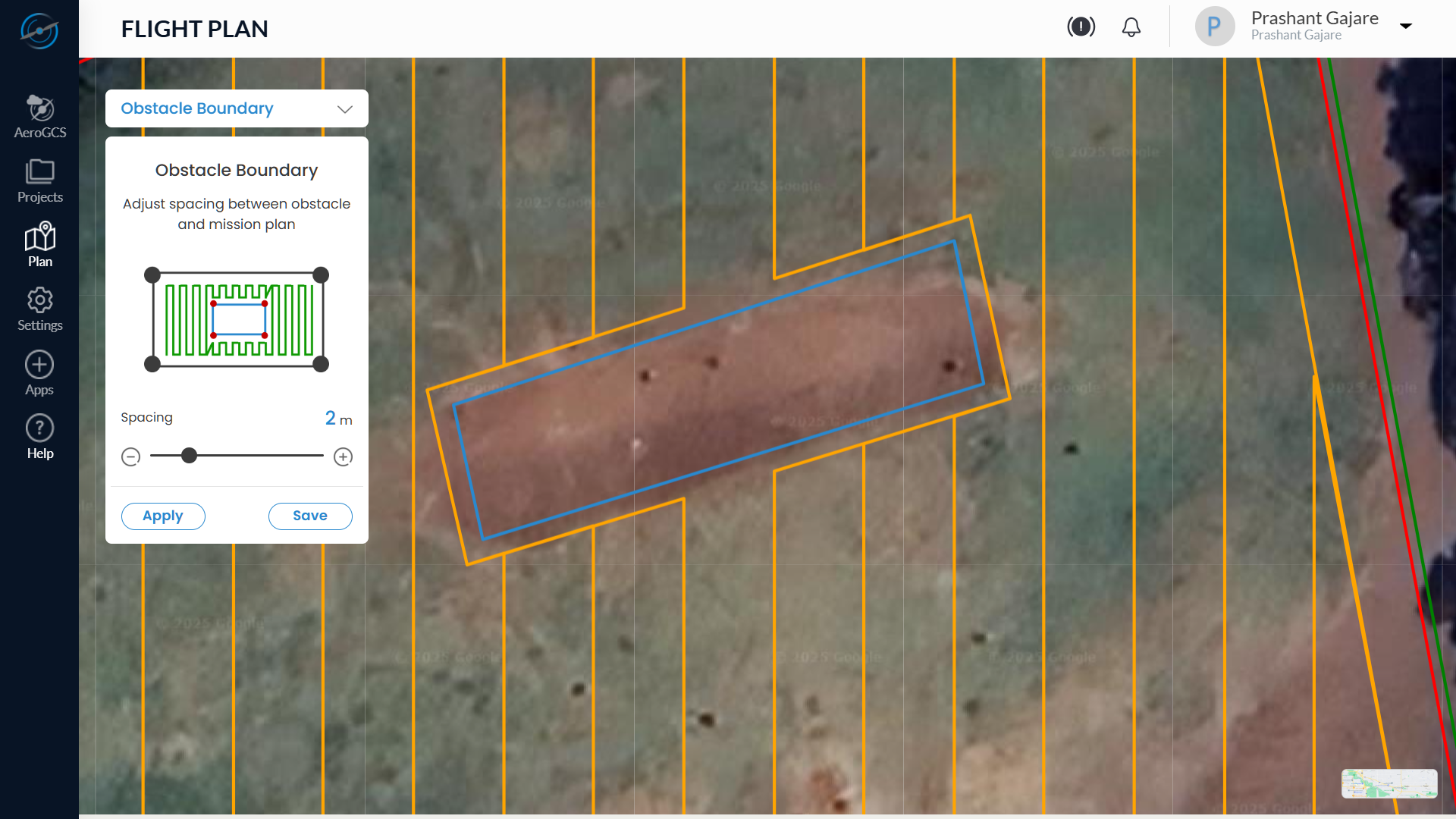
3. Adjust the spacing between the obstacle boundary and the mission flight plan using:
- The slider
- The + button to increase distance
- The – button to decrease distance (Maximum limit: 2 m)
4. Click Apply to preview how the flight path shifts to avoid the obstacle.
5.Click Save to confirm and store the updated configuration.
⚠️ Warning: If no buffer is applied, flight lines may intersect with no-fly zones, increasing the risk of drone collision or mission failure.
💡 Tip: Always verify that spacing adjustments retain adequate field coverage while maintaining safe clearance from obstacles.
Route Adjust Tool
The Route Adjust Tool allows you to rotate the entire flight path grid to align with crop rows, terrain contours, or field geometry. This improves spray coverage efficiency and minimises unnecessary turning.
Steps to Use the Route Adjust Tool:
1. Select Route Adjust from the Tools dropdown.
2. The Route Adjust panel opens, displaying:
- A compass dial with cardinal directions (N, S, E, W)
- A directional arrow that rotates as you adjust the angle
- An angle control slider
- + / – buttons for precise rotation input
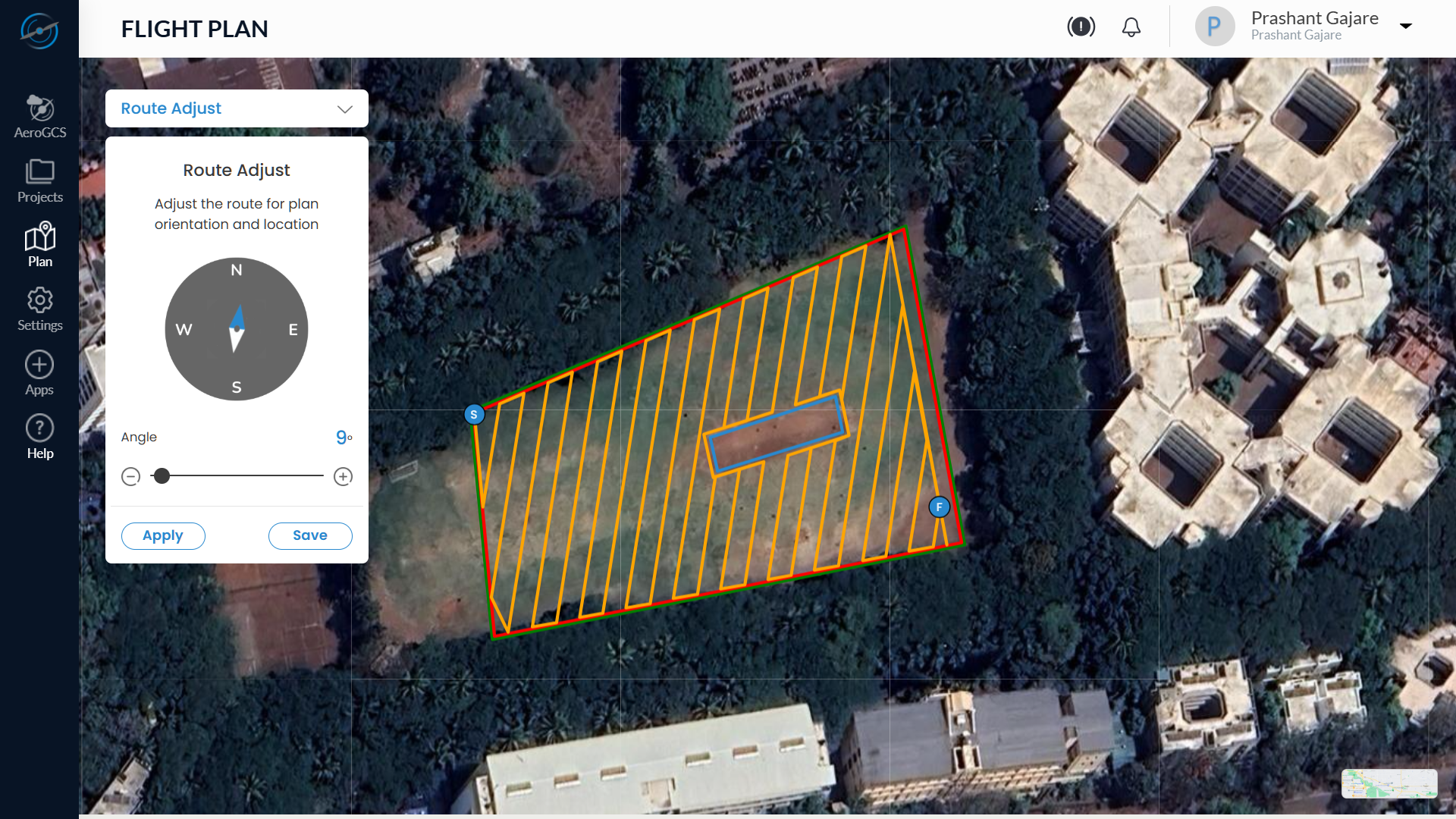
3. Use one of the following methods to change the grid orientation:
- Slide the angle control to rotate the plan from 0° to 360°
- Click the + or – buttons to increase or decrease the angle in smaller increments
4. The directional arrow on the compass rotates as the angle changes, helping you visually align the grid with the desired orientation.
5. Click Apply to preview the rotated path on the map.
6. Click Save to confirm and update the flight plan with the new orientation.
💡 Tip: Aligning the plan with natural field orientation or crop rows improves efficiency, saves battery life, and reduces time spent on unnecessary turns.
⚠️ Note: Over-rotation may cause overlap with boundaries or obstacles. Review the grid after adjusting.
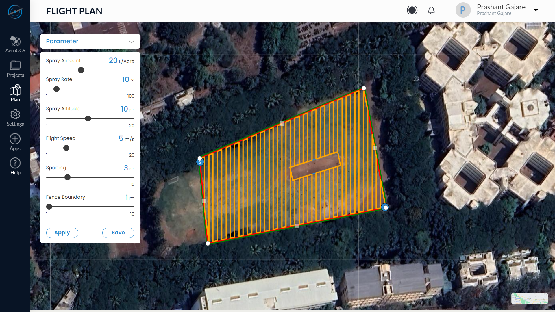
Parameter Tool
The Parameter Tool allows you to configure key flight and spray parameters that influence coverage quality, mission efficiency, and payload usage. All values are adjusted using slider controls in a guided vertical layout.
Steps to Use the Parameter Tool:
1. Select Parameter from the Tools dropdown.
2. The Parameter panel appears, displaying the following configuration options in order, each with a slider bar for adjustment:
Parameter | Description | Range |
Spray Amount | Liquid quantity to be | e.g., 20 L/acre |
Spray Rate (%) | Flow rate as a percentage | 1% – 100% |
Spray Altitude | Height above ground at | 1 – 20 m |
Flight Speed | Speed of drone movement | 1 – 20 m/s |
Spacing | Distance between consecutive | 1 – 10 m |
Fence Boundary | Margin between flight | 1 – 10 m |
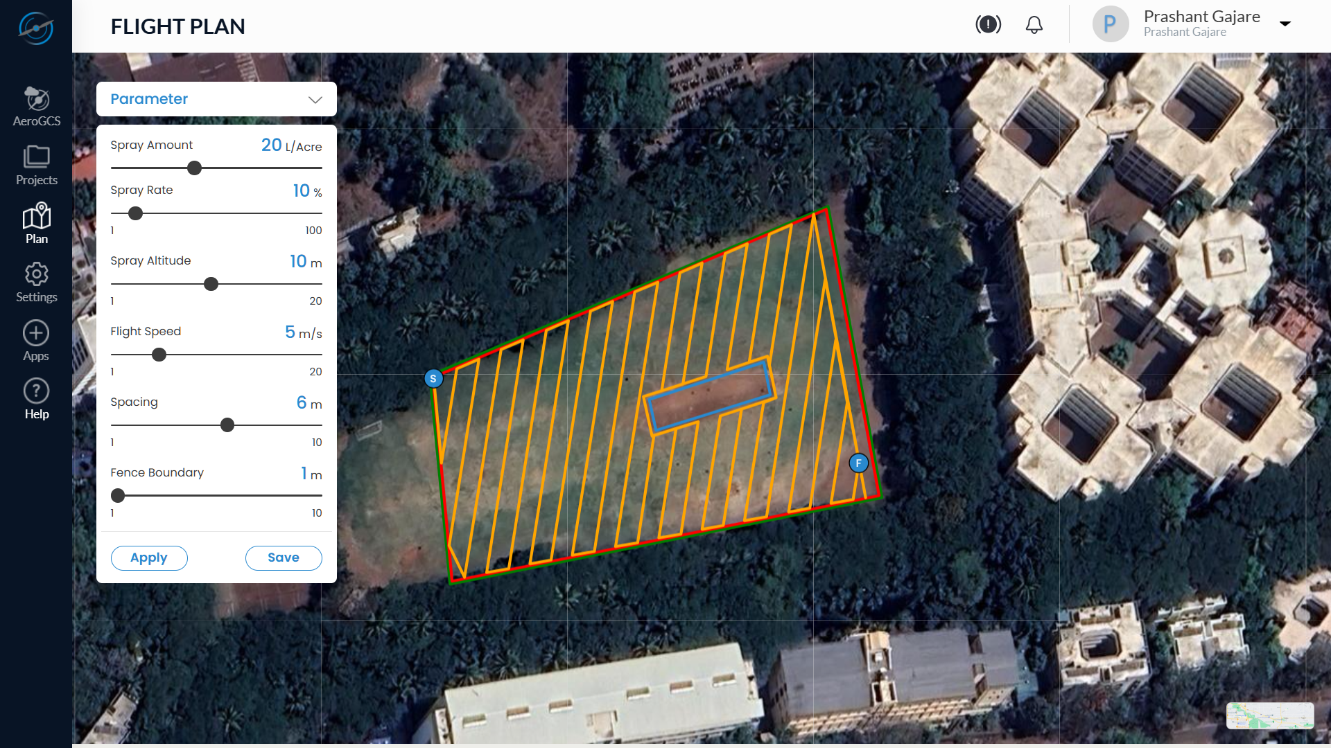
3. To adjust any parameter:
- Move the slider knob left or right until the desired value is shown.
- Each change updates the corresponding visual representation on the map.
4. Click Apply to preview how changes affect the flight plan.
5. Click Save to confirm the new settings.
💡 Tip: Always fine-tune parameters based on terrain type, drone capability, and crop-specific requirements. Slower speed + lower altitude = higher coverage accuracy.
⚠️ Note: Setting improper values may affect mission efficiency or battery consumption. Review all parameters before saving.
Final Tips
- All changes made using the tools must be Applied first and then Saved to ensure they take effect.
- To reset a change, re-select the tool, adjust the value, and Apply/Save again.
- Combine multiple tools for full customisation based on your field, obstacle layout, and flight objectives.
Step 7: Save the Project
- After all route adjustments and parameter settings are complete, click the Save button.
- A Please Wait message will appear.
- On success, a Completed confirmation is displayed.
- The project now appears under the Projects List and is ready for execution or assignment.
8.4 Managing Existing Projects
Edit, Extend, or Reconfigure Previously Created Drone Missions
Once a project is created in AeroGCS Enterprise, users can continue managing it by adding new plots or plans, editing existing configurations, or removing components that are no longer required. This section provides step-by-step instructions to help users access, update, and maintain projects effectively throughout their operational lifecycle.
Note: To delete a plot or flight plan from a project, refer to the respective editing sections:
- 8.4.2 – Editing Existing Plots – for deleting a plot
- 8.4.3 – Editing Existing Plans – for deleting a flight plan
Each deletion process is documented contextually, along with relevant warnings and confirmation prompts.
8.4.1 Accessing an Existing Project
Follow the steps below to locate and open an existing project:
Step 1: Open the Projects Module
- From the left-hand sidebar, click on the Projects icon.
- The Projects list view will open, displaying all projects in tabular format.
Step 2: Locate the Project
You can use multiple options to locate a project efficiently:
- Search: Type the project name in the Search Projects field.
- Date Filter: Use the calendar filter to narrow results by creation date.
- Sort: Click the Name or Date Created column header to sort the list.
Step 3: Navigate Between Pages
If your project list spans multiple pages:
1. Use the pagination controls at the bottom right:
- Click next (→) or previous (←) to browse pages.
- Use numbered buttons to go directly to a specific page.
2. To jump to a specific page:
- Enter the page number in the “Jump to” box at the bottom left.
- Click Go to load that page.
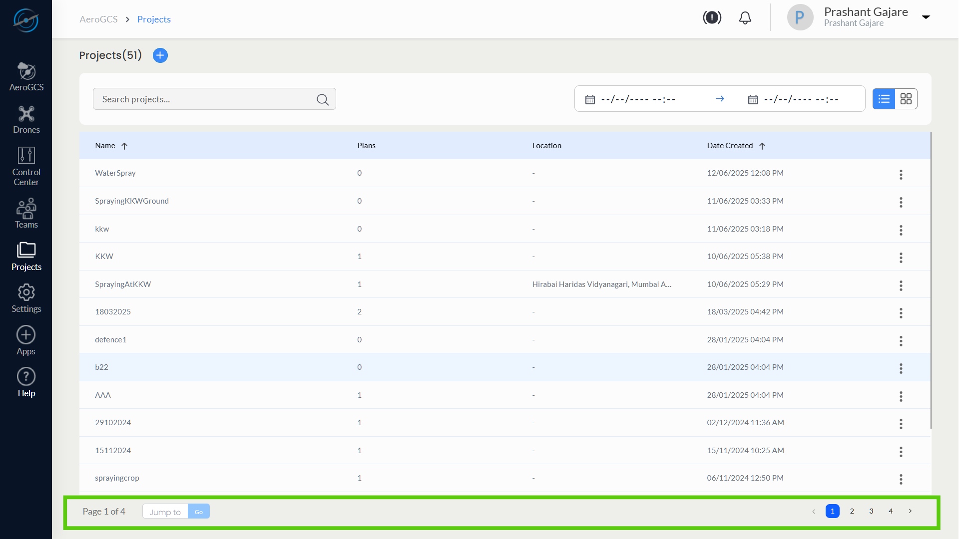
💡 Tip: Use the Jump feature for faster access when managing a large number of projects.
Step 4: Open the Project Details Page
- Find the desired project in the list.
- Click directly on the Project Name,
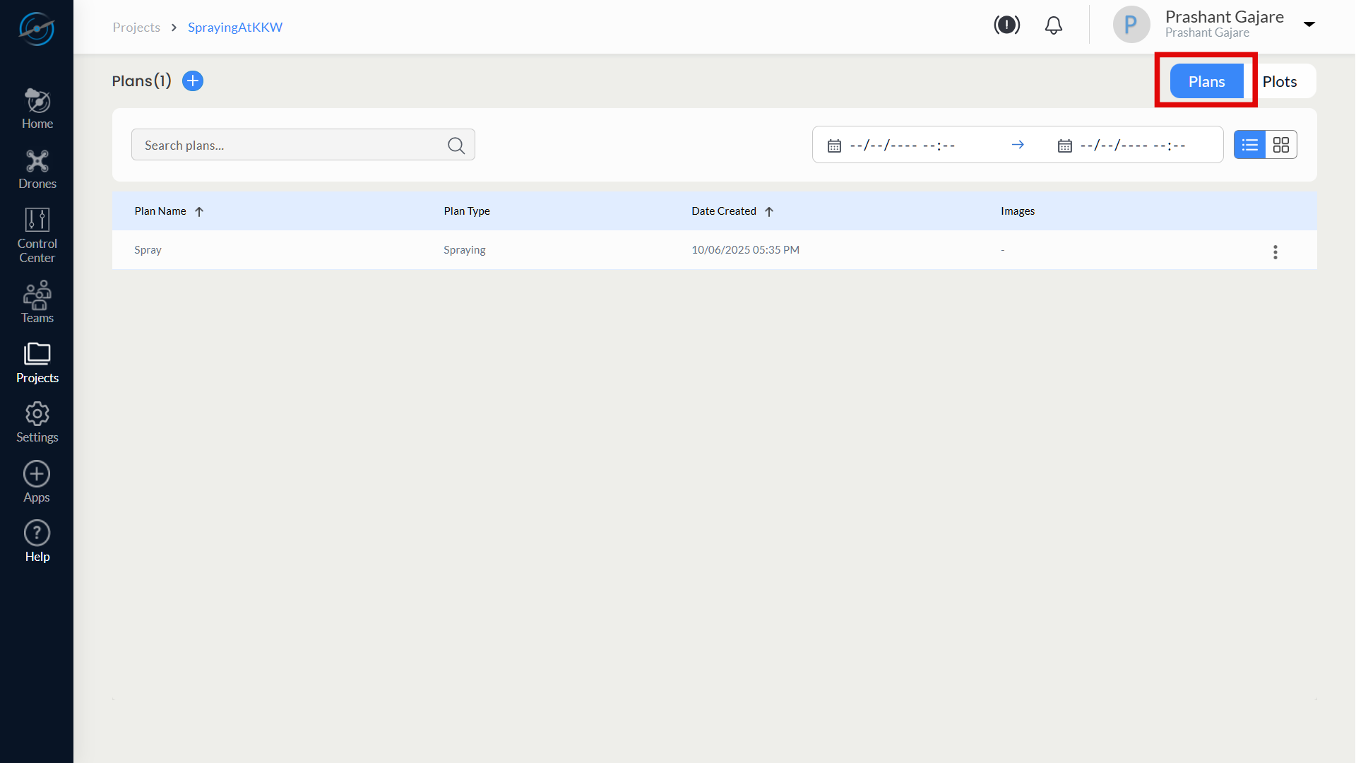
Step 5: Navigate Within the Project
Once inside the Project Details Page, you can access various sections such as:
- Overview – Project name, creation date, and metadata
- Plots – Polygon boundaries and obstacles
- Plans – Flight mission parameters and tools
Use the Plans and Plots buttons in the top-right corner to toggle between plot configurations and mission plans.
Click any tab or section link to begin editing or reviewing that portion of the project.

8.4.2 Editing Existing Plots
Update Plot Boundaries, Obstacles, or Geometry for Existing Missions
After a project has been created, users may need to revise a plot—for instance, if the field boundary changes, obstacles are redefined, or flight zones need to be redrawn. AeroGCS Enterprise enables easy editing of existing plots directly within the project workspace.
Steps to Edit a Plot
Step 1: Open the Plots Tab
- Navigate to the desired project from the Projects List.
- Inside the project, click the Plots button located at the top-right corner of the screen.
- This displays a list of all plots associated with the project.
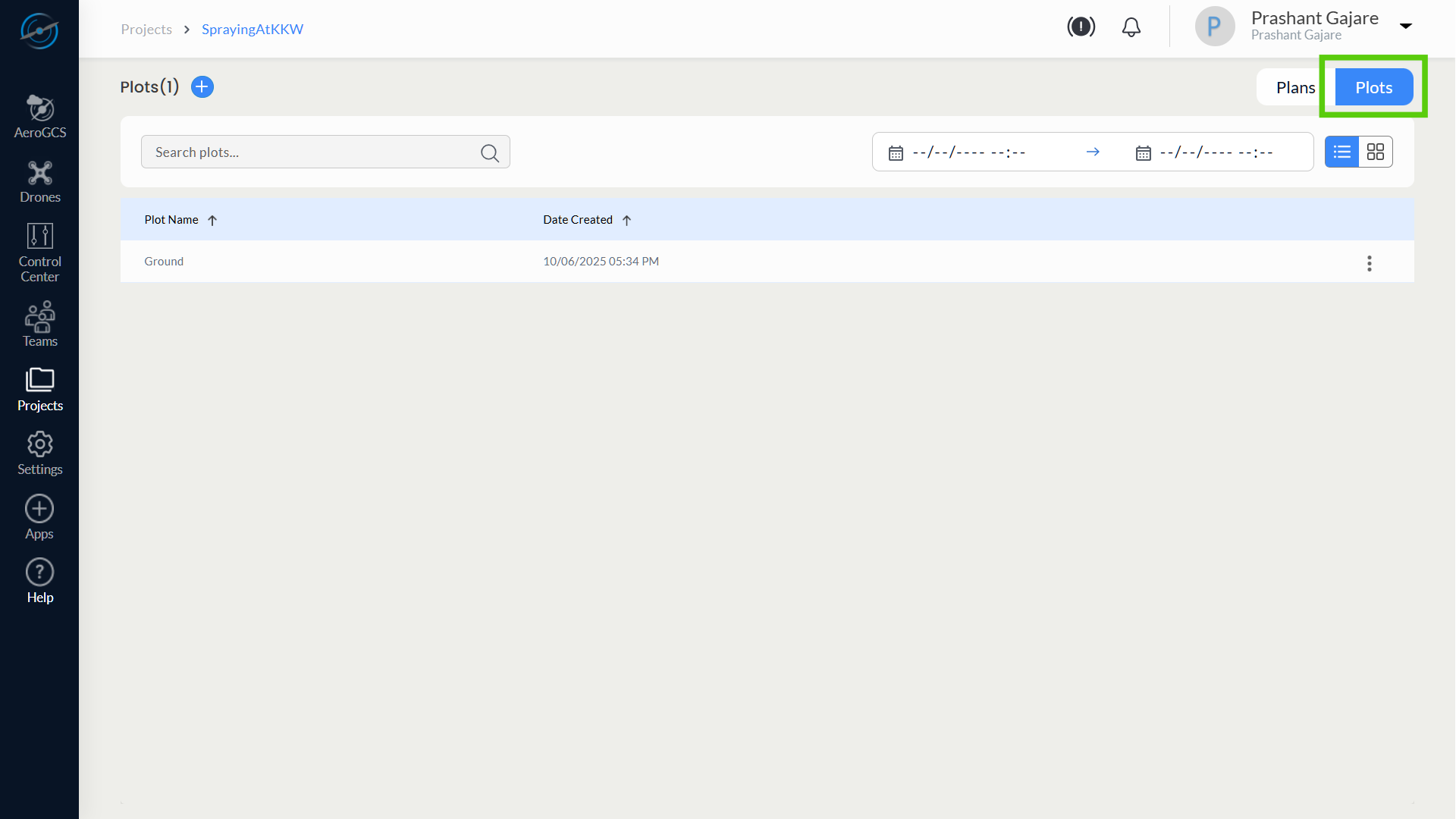
Step 2: Select the Plot to Edit
- Locate the plot you wish to edit from the list.
- Click directly on the Plot Name to open it in edit mode.

💡 Tip: Each plot is named during creation; use consistent naming to find it easily later.
Step 3: Modify the Plot Boundary
Once the plot opens, the map view will display the previously drawn plot boundary.
Click anywhere in between the plot to enable the points of the plot for editing.
You can now:
- Drag existing corner points to adjust shape
- Delete and redraw the plot using the Clear button
- Add or remove obstacles using the toggle controls (see Section 8.3.5)

Note: Ensure the new plot boundary does not overlap no-fly zones or extend beyond the intended area of operation.
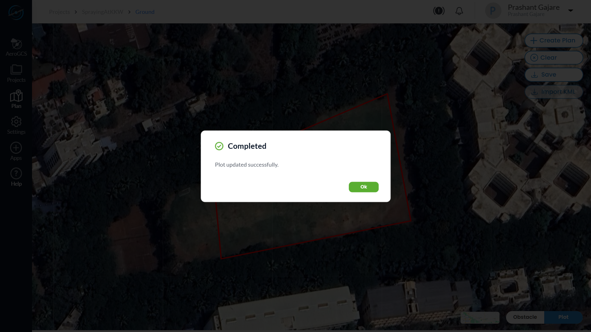
Step 4: Save Changes
After making adjustments:
- Click the Save button at the right top of the map view.
- It shows Save plot with project name and plot name (both are non editable).
- Click the Save button.
- A confirmation message such as “Plot updated successfully” will appear.
- Click on Ok button to continue.
Deleting a Plot
To delete a plot from the project:
- In the Plots list, locate the desired plot.
- Click the three-dot menu (⋮) at the far-right of the row.
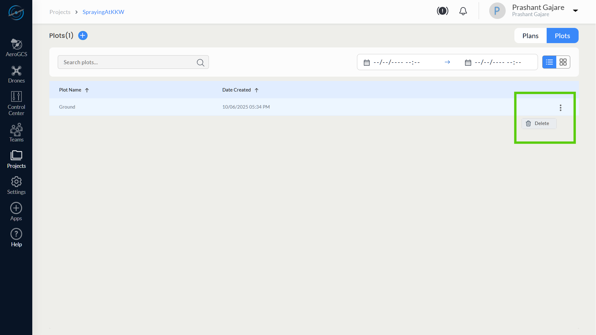
3. Select Delete from the dropdown.
4. Confirm the deletion when prompted.

5. Click Yes to confirm the plot delete.
⚠️ Warning: Deleting a plot will also remove any plans that rely exclusively on it.
Summary
Action | Instruction |
Edit a Plot | Click plot name → adjust boundary → save |
Redraw a Plot | Use Clear button → re-plot → save |
Add/Remove Obstacles | Use toggle tools within map interface |
Delete a Plot | Use ⋮ menu → select Delete → confirm |
8.4.3 Editing Existing Plans
Update or Remove Flight Parameters, Grid Layout, and Mission Settings
AeroGCS Enterprise allows users to modify or remove previously created flight plans within a project. This includes adjusting flight type, grid orientation, mission parameters, or deleting obsolete plans.
Steps to Edit a Plan
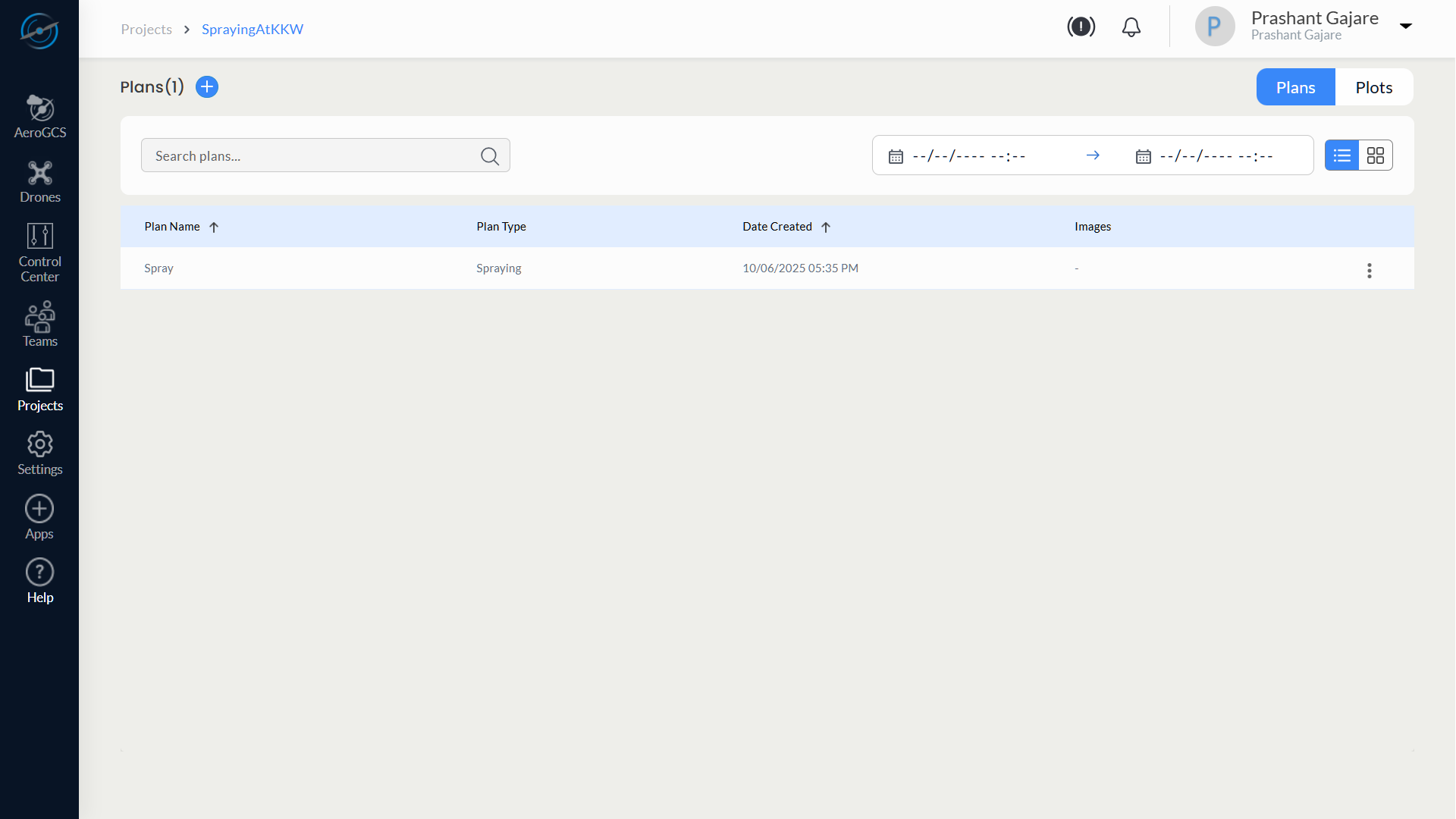
Step 1: Open the Plans Tab
- From the opened project, click the Plans button at the top-right of the Project Details page.
- A list of all flight plans in the project will be displayed in table format.
Step 2: Open the Edit Option
- Locate the plan you want to edit in the list.
- Click the three-dot menu (⋮) at the right end of the plan row.
- Select Edit from the dropdown menu.
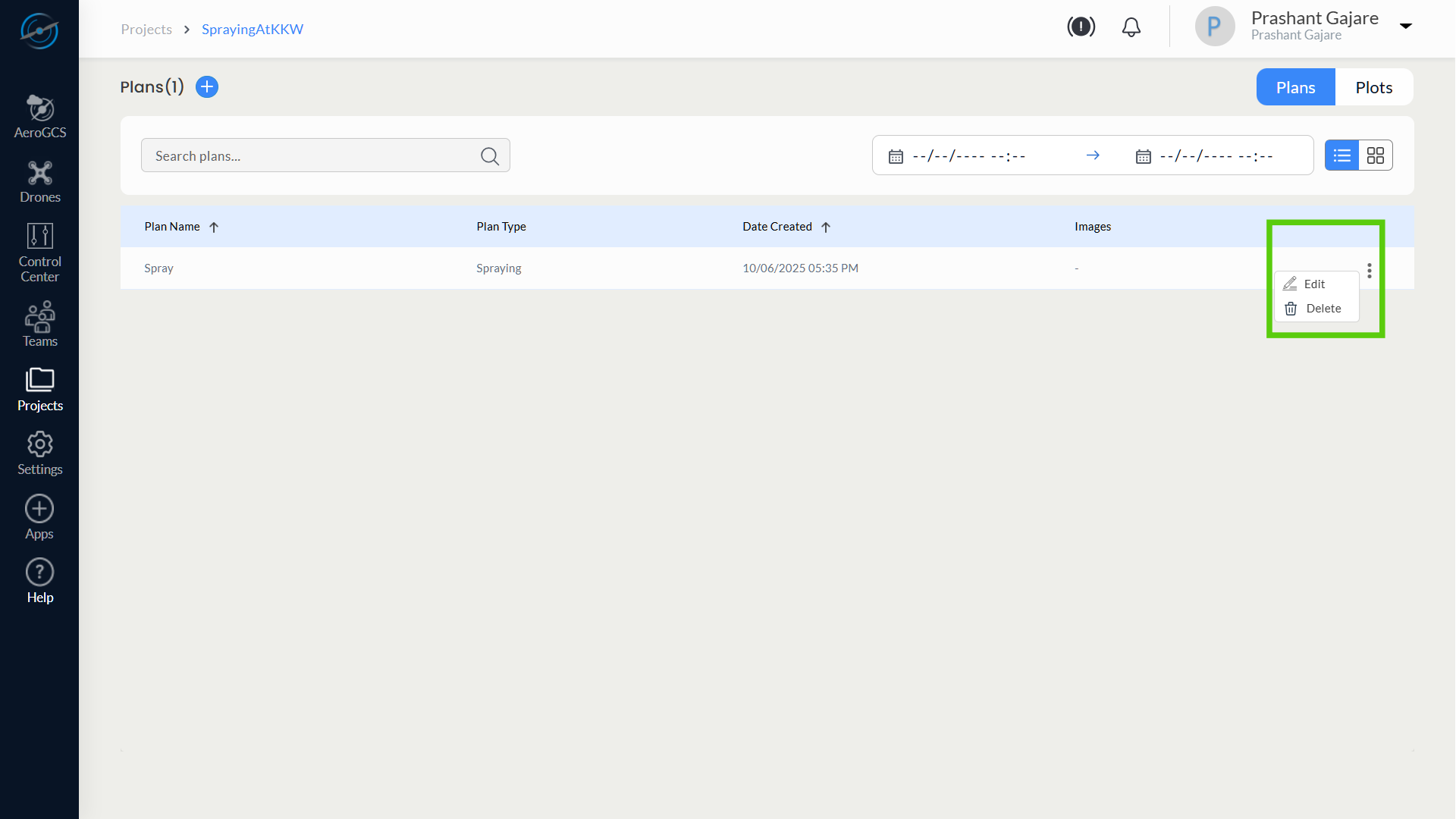
💡 Tip: The same menu also provides the option to Delete a plan (see below).
Step 3: Review and Modify Plan Settings
The selected plan opens with its previously saved configuration.
You can now update:
– Flight Parameters – Adjust:
- Altitude
- Flight Speed
- Spray Amount and Rate
- Spacing and Fence Boundary
– Grid Layout Tools – Use tools such as:
- Waypoint – shift path alignment
- Spacing / Indentation – fine-tune row spacing and margins
- Route Adjust – rotate the flight grid
- Obstacle Boundary – set path clearance from obstacles
🔗 For detailed steps and tool behaviour, refer to Section 8.3 – Step 6: View and Configure Flight Plan.
⚠️ Note: Editing the plan replaces the previously saved configuration.
Step 4: Apply and Save Changes
- After each modification, click Apply to preview.
- Click Save to confirm and persist the updated settings.
Deleting a Plan
If a flight plan is no longer needed, it can be deleted as follows:
- In the Plans tab, locate the plan to be deleted.
- Click the three-dot menu (⋮) next to the plan entry.

3. Select Delete.
4. This will show a message dialog “Are you sure you want to delete this plan?”

5. Confirm the deletion by clicking “Yes”.
6. This will delete the plan.
⚠️ Warning: Deleting a plan is irreversible and will permanently remove associated configurations.
Summary
Action | Instruction |
Access Plan | Projects → Open Project → Click Plans |
Edit Plan | Use ⋮ menu → Select Edit → Modify tools and values |
Apply + Save | Click Apply to preview → Save to confirm changes |
Delete Plan | Use ⋮ menu → Select Delete → Confirm removal |
8.4.4 Adding a New Plot to an Existing Project
Extend Project Coverage by Defining Additional Plot Boundaries
You can add one or more plots to an existing project in AeroGCS Enterprise to support operations that span multiple fields or require separate mission areas. Each plot functions independently and can be linked to its own flight plan.
Steps to Add a New Plot
Step 1: Open the Target Project
- Go to the Projects module and open the desired project (see Section 8.4.1 for access steps).
Step 2: Open the Plots Tab
- On the Project Details page, click the Plots button in the top-right corner.
- A list of existing plots within the project will be displayed.
Step 3: Click + Add Plot
- Click the + Add Plot button.
- The system opens a map interface to define the new plot.
Step 4: Define Plot Boundary and Obstacles
Follow the same steps described in Section 8.3 – Step 5: Create Plot and Define Boundaries:
- Click to draw the boundary points of the plot.
- Close the shape by clicking on the first point.
- Use toggle tools to switch to Obstacle Mode and define:
– Polygon or Circular obstacle zones (optional). - Use the Clear button to restart if needed.
💡 Tip: Use satellite view for precise field boundary alignment.
Step 5: Save the Plot
- Click Save Plot.
- Enter a unique Plot Name if prompted.
- A confirmation message will indicate successful plot creation.
Summary
Action | Instruction |
Access Project | Open existing project from Projects list |
Go to Plots Tab | Click “Plots” at top-right of Project Details page |
Add New Plot | Click “+ Add Plot” to launch map interface |
Draw Plot | Refer to Section 8.3 – Step 5 for detailed boundary/obstacle steps |
Save | Click Save Plot → Provide unique name |
8.4.5 Adding a New Plan to an Existing Project
Configure Additional Flight Missions Based on New or Existing Plots
AeroGCS Enterprise allows you to associate multiple flight plans with a single project. Each plan can target a specific plot and use distinct mission parameters (e.g., altitude, speed, spray amount). This is especially useful when the same field requires different types of coverage or multiple passes.
Steps to Add a New Plan
Step 1: Open the Target Project and Switch to Plans Tab
- Navigate to the Projects module and open the desired project
(see Section 8.4.1 for project access). - Click the Plans button at the top-right of the Project Details page.
Step 2: Click + Add Plan
- Click the + Add Plan button.
- A new flight plan wizard will open, allowing you to configure the mission.
Step 3: Configure the Plan
Follow the same guided steps as described in
Section 8.3 – Step 4 to Step 6: Add Plan Details and Configure Flight Plan:
- Select Flight Type: Waypoints, Survey, or Spraying
- Set Parameters: Altitude, Speed, Spray Amount, etc.
- Generate Grid: The system will auto-generate a flight plan
- Use Tools: Adjust path using Waypoint, Spacing, Indentation, etc.
💡 Tip: Each plan is linked to a specific plot. Ensure the plot is already created (see Section 8.4.4).
Step 4: Apply and Save
- Use Apply in each tool panel to preview the changes.
- Click Save to confirm the new flight plan.
Summary
Action | Instruction |
Open Project | Use Projects module → Open the target project |
Go to Plans Tab | Click “Plans” on Project Details page |
Add New Plan | Click “+ Add Plan” to begin the flight plan setup |
Configure Plan | Follow Steps 4–6 from Section 8.3 to set flight type and parameters |
Save Plan | Apply and Save to finalise the plan configuration |
8.5 Managing Access
Assign and control access permissions for projects in AeroGCS Enterprise by configuring user roles such as Owner, Manager, Pilot, and Guest. Access management ensures that only authorised team members can create, modify, or view project elements.
Purpose
This feature allows you to share a project with registered team members and assign them specific access roles based on their responsibility in the drone operation workflow.
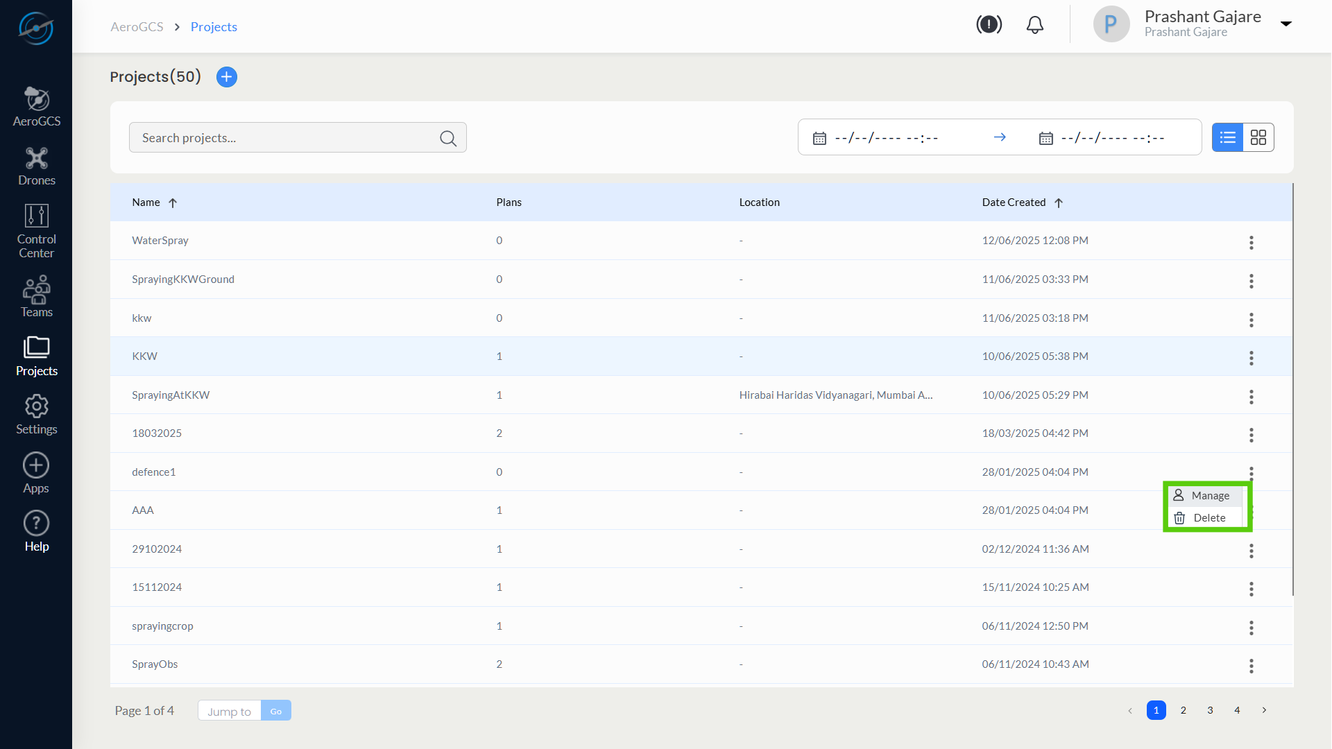
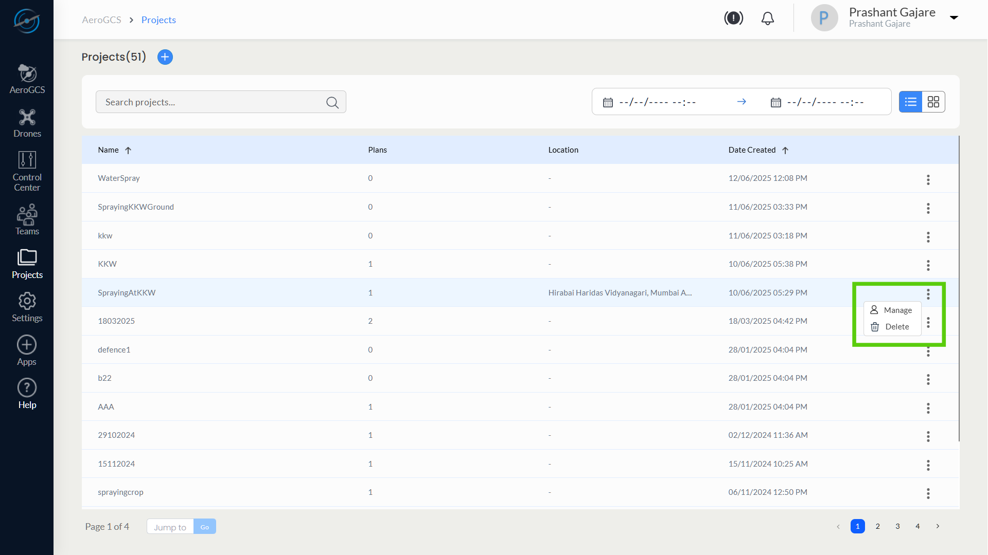
Accessing the Manage Access Option
- Navigate to the Projects module from the left sidebar.
- In the Projects list, locate the desired project row.
- Click the three-dot menu at the end of the row.
- Select Manage to open the Manage Access window.
Assigning Access to Team Members
- In the Manage Access window, use the Search User box to find a registered team member.
- In the dropdown next to their name, select one of the role.
– Manager
– Pilot
– Guest - Click the + (Add) button to assign the selected role.

Only users who are part of your team and registered on AeroGCS Enterprise can be assigned roles.
Removing or Changing Access
- To remove access, click the – (Remove) button next to the user’s name.
- To change a user’s role, first remove the current role using the – button, then:
– Re-select the new role from the dropdown.
– Click the + button to assign the updated role.
Access Notifications
When access is granted, removed, or changed, the concerned user receives a notification in their AeroGCS Enterprise dashboard.
Role-Based Access Matrix
The table below outlines the permissions associated with each role:
Feature / Action | Owner | Manager | Pilot | Guest |
Create Project | ✓ | ✗ | ✗ | ✗ |
Create / Edit Plans & Plots | ✓ | ✓ | ✗ | ✗ |
View Plans / Plots | ✓ | ✓ | ✓ | ✓ |
Drone Control Center Access | ✓ | ✗ | ✗ | ✗ |
Drones Access | ✓ | ✗ | ✗ | ✗ |
Delete Projects | ✓ | ✗ | ✗ | ✗ |
Delete Plans / Plots | ✓ | ✗ | ✗ | ✗ |
💡 Tip: Assign the Manager role to users who need to configure plots or plans but should not have deletion privileges.
Summary
Action | How to Perform |
Open Manage Access | Projects page → 3-dot menu → Manage |
Assign a Role | Search user → Select role → Click + |
Remove Role | Click – next to assigned user |
Change Assigned Role | Remove (–) → Select new role → Click + |
Notification of Role Change | Automatically sent to user on assignment/removal |
Valid Users | Must be registered and part of the current AeroGCS Team |
8.6 Deleting a Project
Permanently Remove a Project and All Associated Data
AeroGCS Enterprise allows users to delete a project when it is no longer needed. This action permanently removes the project along with its associated plots, plans, and related configurations. This operation is typically restricted to users with Manager-level access or equivalent permissions.
⚠️ Important Notice
Deleting a project is irreversible. All plots, flight plans, and mission configurations under that project will be permanently lost.
Make sure to export any required data or reports before proceeding.
Steps to Delete a Project
Step 1: Open the Projects Page
- Navigate to the Projects section using the sidebar.
- The Projects list view will be displayed.
Step 2: Locate the Target Project
- Use the Search, Sort, or Pagination controls to find the project you want to delete.
- Once located, go to the far-right side of the project row.
Step 3: Open the Action Menu and Select Delete
- Click the three-dot menu (⋮) corresponding to the project.
- From the dropdown options, click Delete.
Step 4: Confirm Deletion
- A confirmation dialog will appear.
- Review the warning message carefully.
- Click Confirm or Yes, Delete to proceed.

⚠️ Warning: Once deleted, the project and all its contents cannot be restored.
Summary
Action | Instruction |
Open Projects | Use the sidebar to access the Projects module |
Locate Project | Use filters or search to find the project |
Open Action Menu | Click ⋮ → Select Delete |
Confirm Deletion | Read warning → Confirm to proceed |
8.7 Summary of Projects Chapter
Quick Reference for Creating, Managing, and Sharing Projects in AeroGCS Enterprise
The Projects module in AeroGCS Enterprise enables users to define drone missions, manage flight areas, configure plans, and control access. This summary provides a quick reference to all major actions documented in this chapter, along with their required access roles and section references.
Quick Access Table
Action | Role Required | Where to Perform | Section |
Access Projects Module | All Roles | Sidebar Menu | 8.1 |
Create a New Project | Owner | Projects List View → + Create | 8.2 |
Select Location & Drone | Owner | During Project Creation | 8.2.2 / 8.3 |
Configure Flight Plan (Tools) | Owner | Step 6 – Create Project Wizard | 8.3 |
Save and Finalise New Project | Owner | Create Project Interface | 8.3.6 |
Access an Existing Project | All Roles | Projects List → Click/View | 8.4.1 |
Edit Plot or Boundary | Owner, Manager | Project View → Plots tab | 8.4.2 |
Delete Plot | Owner | Plots tab → ⋮ Menu | 8.4.2 |
Edit Plan / Parameters | Owner, Manager | Project View → Plans tab | 8.4.3 |
Delete Plan | Owner | Plans tab → ⋮ Menu | 8.4.3 |
Add New Plot to Existing Project | Owner | Plots tab → + Add Plot | 8.4.4 |
Add New Plan to Existing Project | Owner | Plans tab → + Add Plan | 8.4.5 |
Assign Project Roles to Team Members | Owner, Manager | ⋮ Menu → Manage Access | 8.5 |
Modify or Remove Project Access | Owner, Manager | Manage Access Dialog | 8.5 |
Delete Entire Project | Owner | ⋮ Menu → Delete | 8.6 |
Supported Roles and Permissions
Role | Capabilities Summary |
Owner | Full control: create, edit, delete projects, manage users, drone control, and plans |
Manager | Configure plots/plans; cannot create/delete projects or manage drones |
Pilot | View-only access to plots and plans assigned to them |
Guest | Read-only access to the entire project (no edit/delete) |
For a detailed comparison, refer to the Role-Based Access Matrix in Section 8.5.
When to Use the Projects Module
Use this module whenever you need to:
- Define new mission areas and generate flight plans
- Assign team members to specific projects
- Update or optimise existing mission data
- Remove or clean up completed projects