-
AeroGCS GEEN User Manual
6. Projects
A project in AeroGCS GREEN is a container that holds plans, plots, and related configurations required for safe and accurate drone operations. Projects can be created locally in AeroGCS GREEN or assigned through Teams by a Manager via AeroGCS Enterprise. Access to assigned projects and available actions may vary based on the user’s role and login status. Managing a project involves the following key tasks:
- Project Creation: Creating a new project locally in AeroGCS GREEN.
- Project Access: Opening and viewing existing projects, including projects assigned through Teams via AeroGCS Enterprise.
- Project Modification: Editing or updating project details, plans, or plots, subject to assigned role and Enterprise synchronization rules.
- Project Preservation: Saving project data to retain current configurations and operational progress
6.1 Teams
(Project Collaboration)
6.1.1 Teams Overview
In current scenario, the drone industry works in manual procedure. The management team is seating into the office, the drone pilot team is working on the field by giving the service to the customers (farmers). Hence there is no proper tracking and monitoring of the operations by the management team. Hence we have introduced the Teams functionality in AeroGCS. This functionality is being used to have tracking and monitoring of drone spraying operations by the management team or even by the client.
The Teams feature in AeroGCS GREEN enables controlled project collaboration by allowing users to access only those projects to which they have been explicitly assigned by a Manager through AeroGCS Enterprise.
In AeroGCS GREEN, Teams are represented by Managers. Each manager owns one or more projects and assigns users to those projects with a specific role. Users can view and operate only on projects assigned to them, ensuring controlled access, data consistency, and clear operational responsibility.
Teams’ functionality in AeroGCS GREEN is limited to project access and execution. Team creation, user invitation, and role assignment are managed externally through AeroGCS Enterprise.
6.1.2 Access Requirements
Before using Teams in AeroGCS GREEN, ensure that:
- You are logged in to your AeroGCS Enterprise account from within AeroGCS GREEN. Here AeroGCS Enterprise Account will be of manager or company. Not pilot’s or user’s account.
- A Manager has added you to their team for one or more projects.
- You have accepted the invitation received via email or AeroGCS Enterprise in-app notification.
- An active internet connection is required.
📝 Note: If the invitation is not accepted, the manager and their projects will not appear in the Teams list.
6.1.3 Open Teams
Teams can be accessed directly from the Projects screen.
Steps:
- Open AeroGCS GREEN.
- Navigate to the Projects screen.
- Tap the three-dot (⋮) menu at the top-right corner.
- Select Teams.
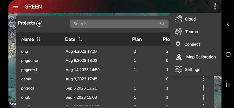
📝 UI Behavior:
The Teams option is available only when the user is logged in to an AeroGCS Enterprise account.
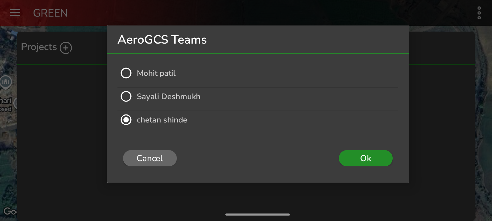
6.1.4 Select Manager and Sync Project
After selecting Teams, the AeroGCS Teams dialog is displayed.
This dialog lists the Managers under whom you have been added as a team member.
- Each entry represents a Manager Team.
- Only one manager can be selected at a time.
- Selection is performed using a radio button.
Steps:
- Select the required Manager.
- Tap OK to confirm the selection.
After confirmation, the list of projects assigned to you under the selected manager is fetched and synchronized at the project metadata level from AeroGCS Enterprise.
Only project metadata is synchronized at this stage.
If the project already contains plans or plots, they are not downloaded automatically and remain on the server until the user opens the project and manually downloads the required plans or plots.
If the synchronized project does not contain any plans or plots, you can create new ones locally by following the standard workflow described in Create Plot and Create Plan under the Projects section of this manual.
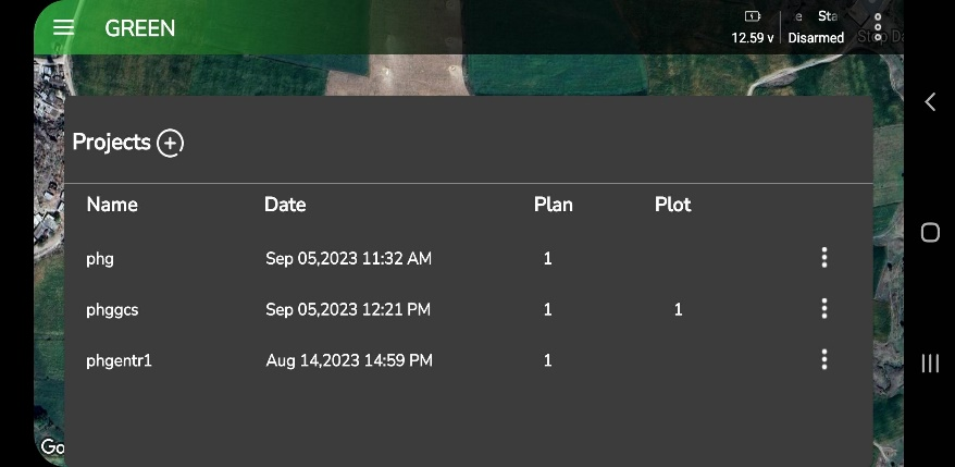
Once metadata synchronization completes, the Projects screen is refreshed to display the assigned projects.
📝 Note:
Project metadata synchronization requires an active internet connection. Downloading plans and plots is described separately in Section 6.3.6 Download Plot and Plan.
6.1.5 Assigned Projects and Roles
After synchronization, AeroGCS GREEN displays the list of projects assigned to you by the selected manager.
Only projects for which you have been explicitly added as a team member are visible. Others project to which you are not assigned, are hidden and cannot be accessed.
When you select a project from the list, the Project View screen opens. On this screen, your assigned role is displayed next to the project name, for example:
- ProjectName (Role)
The role is project-specific and determines the level of access available to you within that project.
Select the project and proceed with your work according to the assigned role.
📝 Note:
Project roles are assigned and managed through AeroGCS Enterprise and cannot be modified from AeroGCS GREEN.
6.1.6 Working with Team Projects
Once a project is opened through the Teams flow:
- The project behaves the same as a standard project.
- You can create plots, generate plans, execute missions, and generate reports based on your assigned role.
- The operational workflow remains unchanged after project selection.
➡ Reference:
For detailed procedures, refer to:
- 6.2 Create a New Project
- 6.3 Handling Existing Project
6.1.7 Notes and Limitations
- Users cannot create teams or invite other users from AeroGCS GREEN.
- Team membership and role assignment are controlled exclusively by the Manager via AeroGCS Enterprise.
- Only one manager’s project list can be viewed and synchronized at a time.
- Internet connectivity is required to synchronize project metadata.
- Logging out of AeroGCS Enterprise disables Teams access.
Operational Reminder:
Always verify the selected manager and your assigned role before starting mission planning or flight execution.
6.1.8 Summary
The Teams feature in AeroGCS GREEN provides a secure, manager-controlled mechanism for accessing assigned projects with clearly defined roles. By synchronizing project metadata only at manager selection and downloading plans or plots on demand, AeroGCS GREEN ensures efficient data usage, controlled access, and consistent integration with AeroGCS Enterprise.
6.2 Create a New Project
To initiate creating a new project in AeroGCS GREEN, access the designated screen by tapping the “Home ![]() ” menu.
” menu.
Step 1: On this screen, simply tap the ![]() i.e “+” sign to commence the process of creating a new project in AeroGCS GREEN. You will see the following screen on your device.
i.e “+” sign to commence the process of creating a new project in AeroGCS GREEN. You will see the following screen on your device.
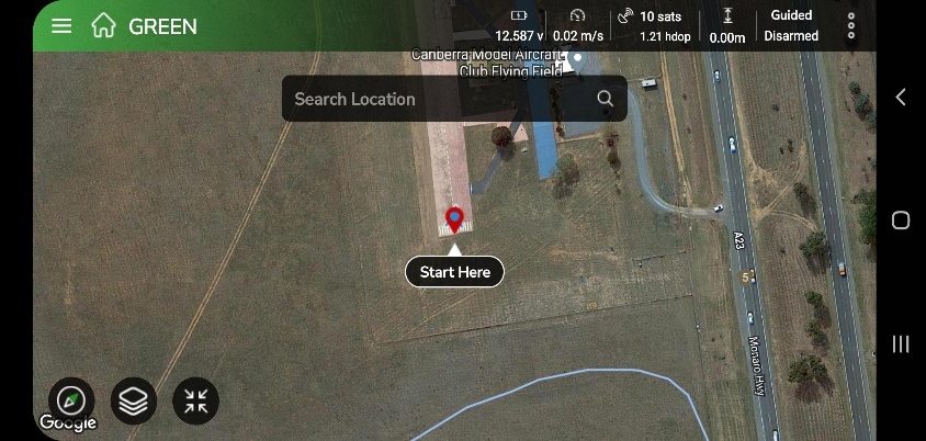
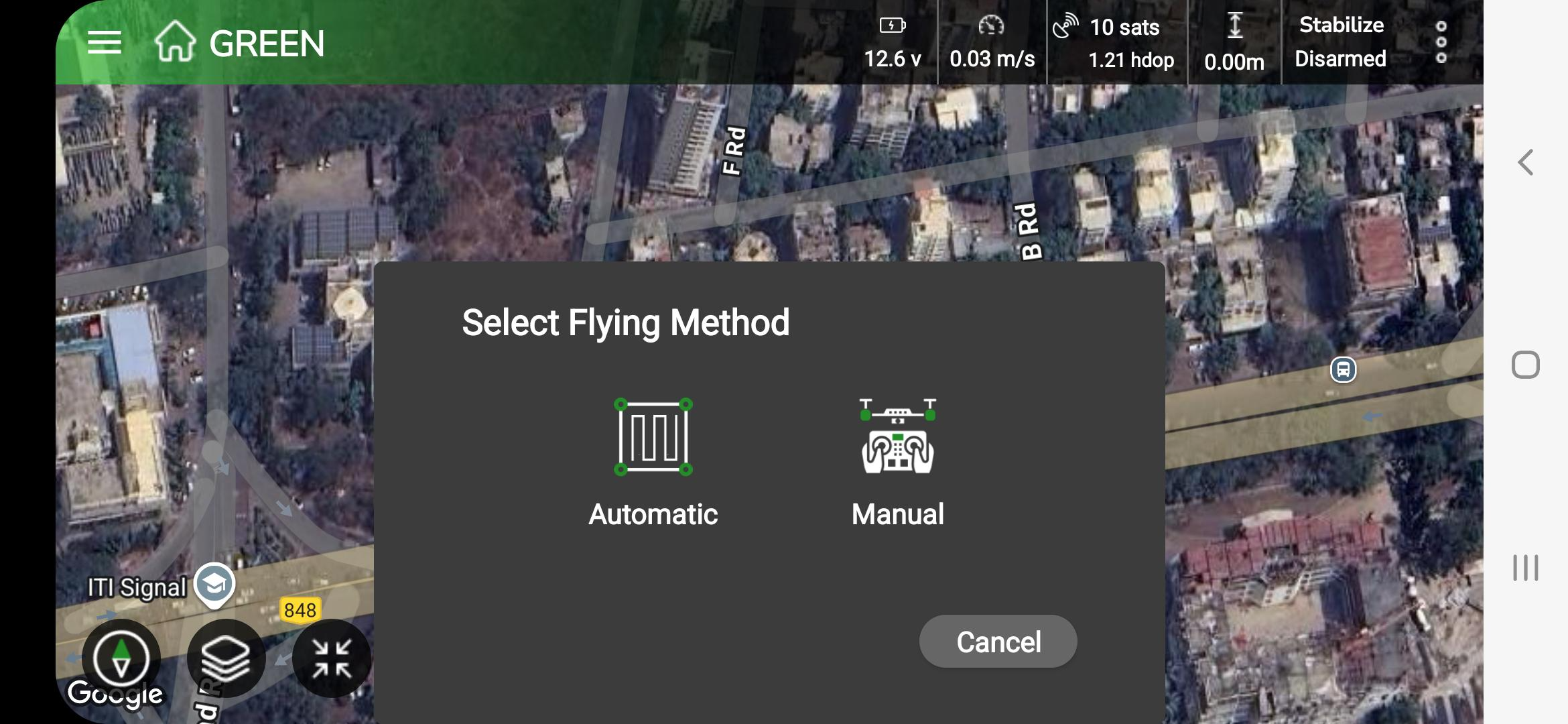
Step 2: Tap on “Start Here”, the screen will display Flying methods “Automatic” and “Manual”. As shown in the following screen. Select your flying method by tapping on the appropriate method.
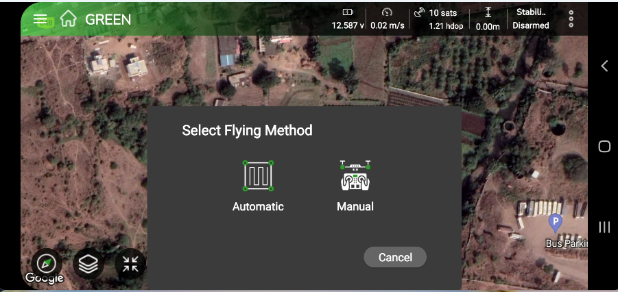
To create a plot, start by choosing a preferred flying method from the available options:
- Automatic Method: With this approach, you can map a field plot on Google Maps.
- Manual Method: In contrast, the manual method allows you to physically Arm the drone to fly manually on the field and then disarm the motors once the desired area has been covered.
6.2.1 Automatic Flying Method
This method is designed for you if you prefer to plot a field using Google Maps. You can use satellite images and map tools to mark your field boundaries. By tapping points on the map, you can outline the exact area you want to define.
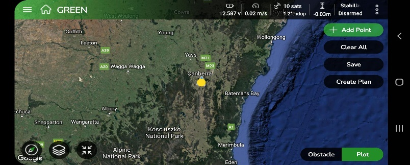
1. Setting Location
Before you begin plotting in AeroGCS GREEN, you need to set your location. Follow these steps to make sure your plotting is accurate:
Step 1: Access the Home Screen
Open the Home screen in AeroGCS GREEN.
Step 2: Locate the Search Option
Find the Search option on the Home screen.
Step 3: Enter Your Desired Location
Type your desired location in the search field.
Step 4: Tap the Search Symbol
After entering your location, tap the Search icon to start the search.
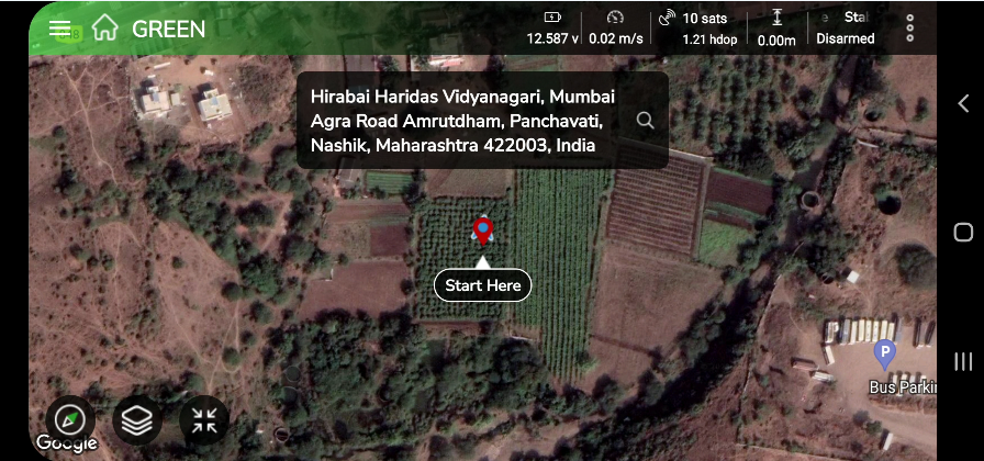
Step 5: Set the Start Location
Review the search results and select the correct location to set it as your starting point for plotting.
Step 6: Confirm the Selection
Confirm your selected location to ensure accurate plotting.
Once you complete these steps, your screen will look like the image shown below. This confirms that your location has been set correctly, and you are ready to start plotting in AeroGCS GREEN.
2. Create a plot
Follow the steps to create a plot.
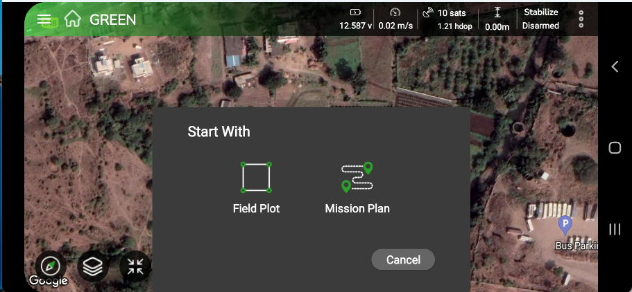
Step 2.1: If you choose the Automatic flying method, the interface will display the following screen and prompt you to select a Start with option from Field Plot or Mission Plan.
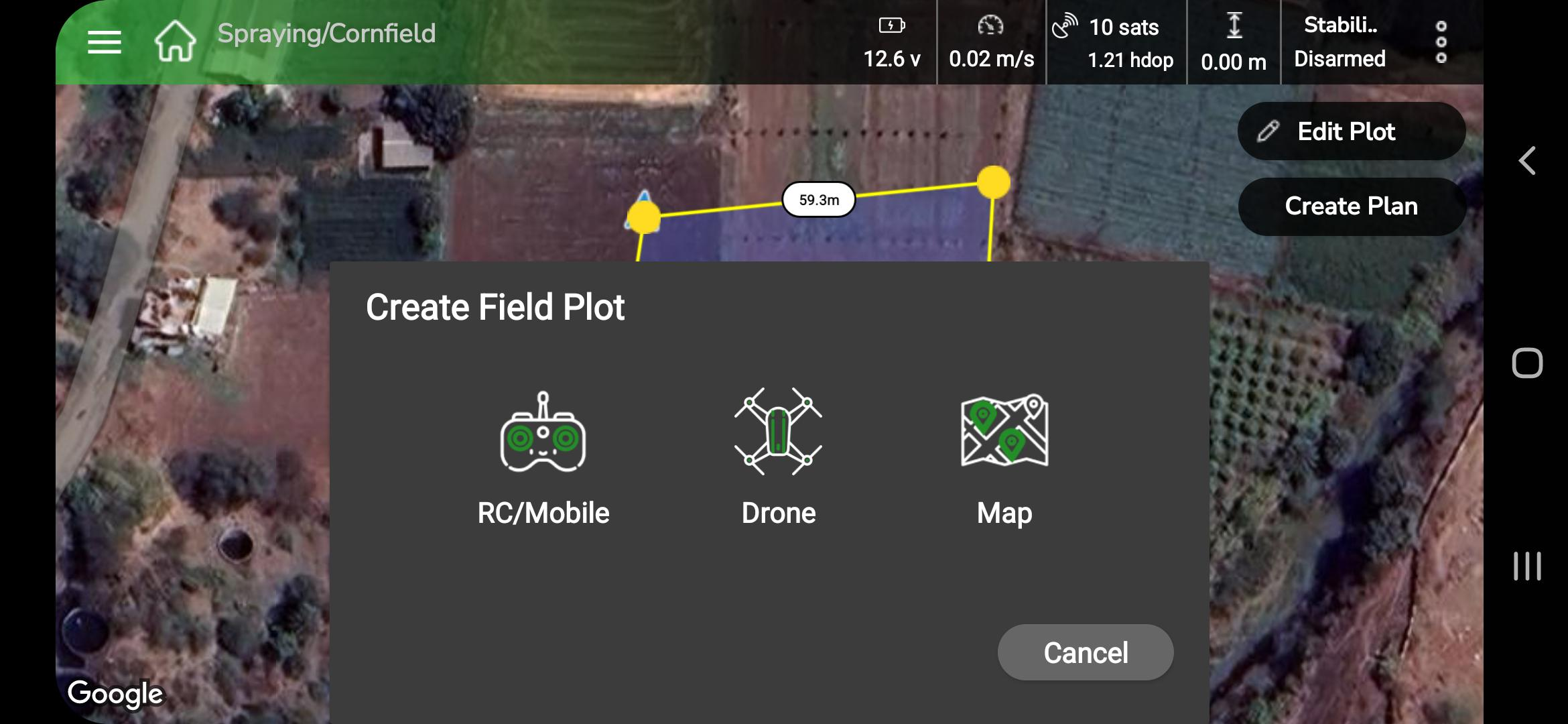
Step 2.2: If you start with the Field Plot option, the system will ask you to choose your preferred method for creating the field plot from the available options, as shown in the following screen.
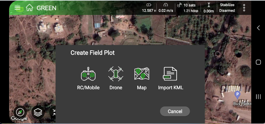
AeroGCS GREEN offers four options for creating a field plot:
- RC/Mobile
- Drone
- Map
- Import KML
| 📝 Note: On the “Start with” pop-up screen, if you select “Mission Planning“, it will display a list of your existing stored projects. |
Field Boundary Marking Using RC or Mobile Device
- Take your RC device or mobile device to the actual field.
- Mark boundary points by moving to specific locations on the ground.
- Walk around the perimeter to outline the entire field with accuracy.
- Once all points are marked, save the plot. It will now be ready for your drone flight.
- This method helps you achieve higher accuracy when defining your plotted area.
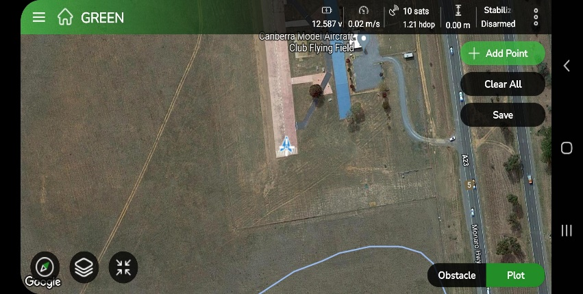
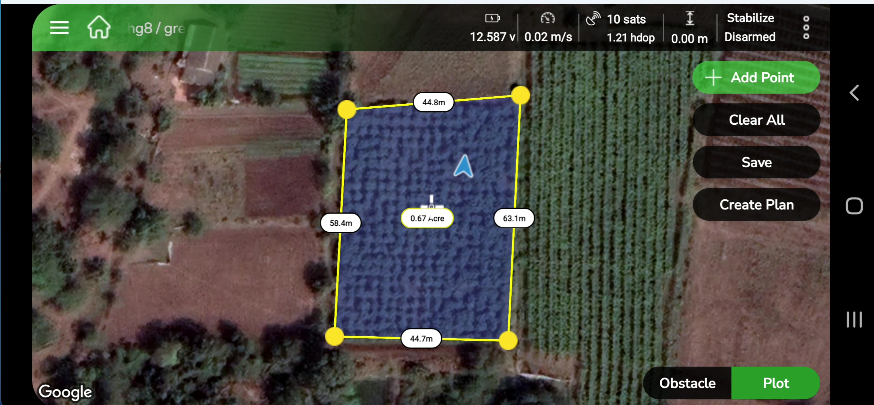
Step 1: After selecting the RC/Mobile option for plot creation using either your RC device or mobile device, the following screen appears on your device.
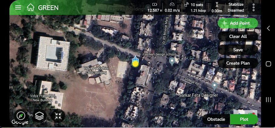
Step 2: Tap +Add Point to place a point on the map. You can continue adding multiple points to your plot, as shown in the following screen.
By default, this view shows the process of plotting points for your plot.
The screen also provides the following options:
- Clear All: Tap Clear All to remove all points from the map.
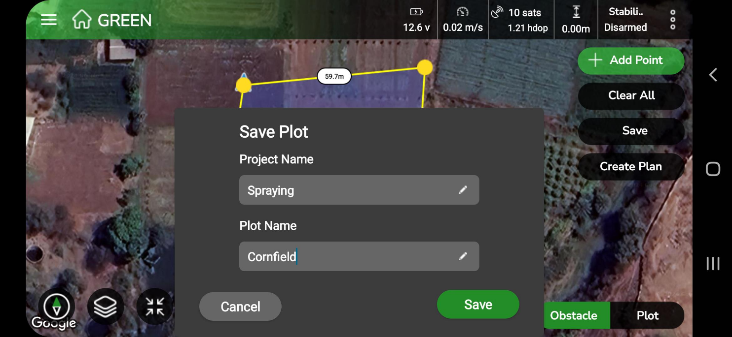
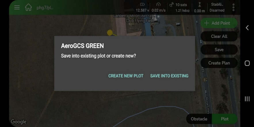
- Save: Tap Save to store your plot for future use.
- Create a Plan: Tap Create Plan to generate a mission plan from the saved plot. Remember, you must save your plot before creating a plan.
- Obstacle: Tap Obstacle to add obstacles to your plot. You can add obstacles in either polygon or circle
4. Drone
Field Boundary Marking Using a Drone
- Just like the RC/Mobile method, you can mark the boundaries of the field plot.
- However, instead of walking around the field, your drone flies overhead and marks the boundaries from an aerial view.
Plotting Using Drone
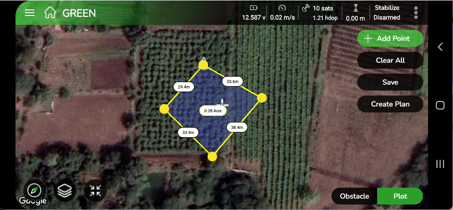
Step 1: After selecting the Drone option for plot creation, the following screen will appear on your device.
Step 2: Tap +Add Point to place a point on the map at the drone’s current location. You can continue adding multiple points to your plot by moving your drone to the next desired location, as shown in the following screen.
By default, this view displays the process of plotting points for your plot.
The screen also includes the following options:
- Clear All: Tap Clear All to remove all points from the map.
- Save: Tap Save to store your plot for future use.
- Create a Plan: Tap Create Plan to generate a plan from your saved plot. Remember to save your plot before proceeding to plan creation.
- Obstacle: Tap Obstacle to add obstacles to your plot. You can add obstacles in polygon or circle
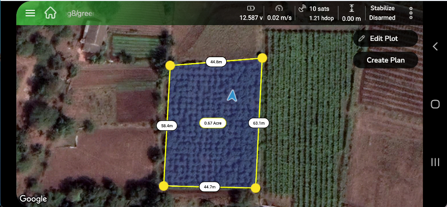
Field Plotting Using Google Maps
- Create field plots directly on Google Maps for enhanced accuracy.
- Use intuitive features like ‘Add Point’, ‘Clear’, and ‘Save’ for easy plotting.
- The interactive map pointer and dynamic background enable precise field boundary marking.
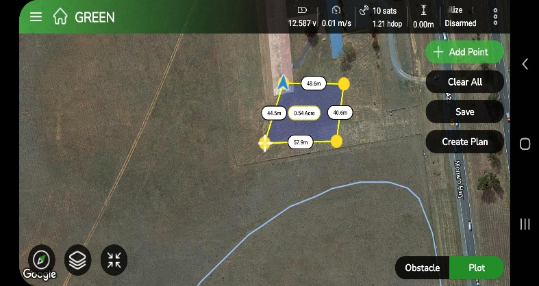
Step 1: After selecting the “Google Maps” option for plot creation, the following screen will appear on the user’s device.

By default, this view displays the process of plotting points for your plot.
The screen also includes the following options:
- Clear All: Tap Clear All to remove all points from the map.
- Save: Tap Save to store your plot for future use.
- Create a Plan: Tap Create Plan to generate a plan from your saved plot. Remember to save your plot before proceeding to plan creation.
- Obstacle: Tap Obstacle to add obstacles to your plot. You can add obstacles in polygon or circle
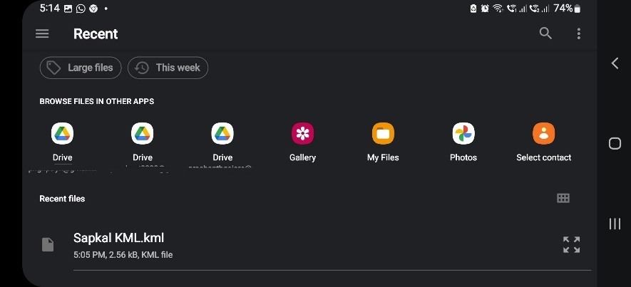
Importing KML Files for Field Plotting
- Users can import KML files to quickly create a field plot.
- These KML files can be sourced from various locations.
Step 1: When you select the KML option to create a plot from a .kml file, the following interface will appear on your screen, prompting you to browse and select the .kml file.
Step 2: After you tap the selected .kml file, the screen will display the map view associated with that file, as shown in the following image.
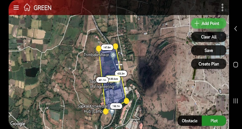
By default, this view displays your plot and shows the process of plotting points using Google Maps.
The screen also provides the following options:
- Clear All: Tap Clear All to remove all points from the map.
- Save: Tap Save to store your created plot for future use.
- Create a Plan: Tap Create Plan to generate a mission plan from your saved plot. Remember, you must save your plot before creating a plan.
- Obstacle: Tap Obstacle to add obstacles to your plot. You can add obstacles in either polygon or circle
| 📝 Note: Before creating a plan, make sure to save the plots you have created to avoid any data loss. |
7. Adding Obstacles to the Plot
An obstacle in drone operations refers to any physical or environmental object that can interfere with the safe flight of a drone. Examples include buildings, trees, power lines, poles, hills, or any other structures that may block the drone’s path or cause a collision. As a drone operator, you must identify and avoid such obstacles to ensure safe and compliant flight, following aviation regulations designed to prevent accidents and protect people and property.
In AeroGCS GREEN, you can add two types of obstacles to your plot:
- Polygon: This type allows you to mark obstacles using polygon shapes at specific points or areas on the map.
- Circle: This type allows you to mark circular obstacles at chosen locations on the map.
How you can add obstacles to your plot?
Step 1: To add an obstacle to the AeroGCS GREEN map, go to the plotting screen and tap the Obstacle button at the bottom. You will then be prompted to choose the type of obstacle, as shown in the following screen.
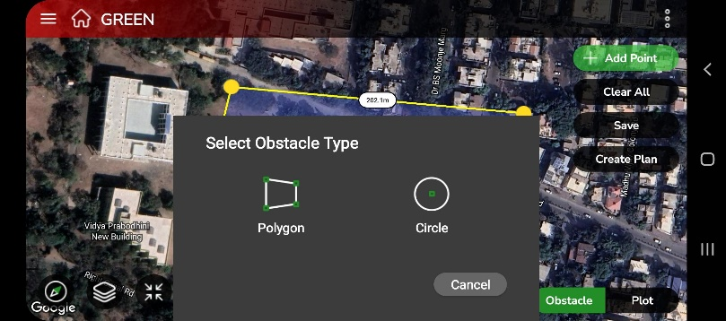
Step 2: Select the type of obstacle you want to add to your plot by tapping either Polygon or Circle.
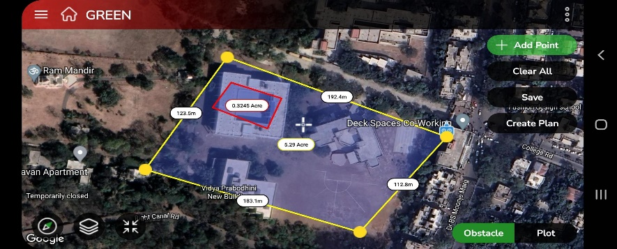
Step 2.1: If you select the Polygon type of obstacle, the screen will appear where you can add obstacle points. Tap +Add Point to start marking points on the map and continue adding all the required points, as shown below.
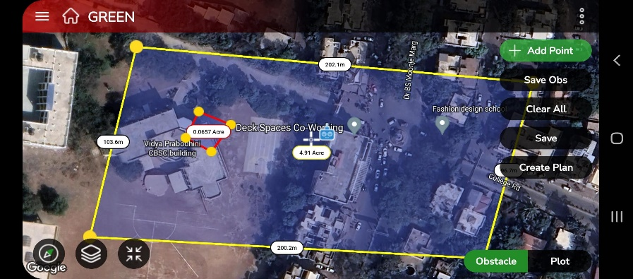
Step 2.2: Once you’ve added all the points for the polygon obstacle, tap Save Obs to save it to your plot. Your screen will then display the following view.
You can add multiple polygon obstacles by repeating Steps 2.1 and 2.2.
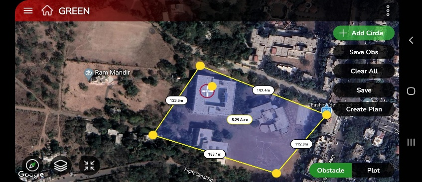
Step 2.3: When you select Circle as the obstacle type, a screen appears for adding a point. Tap +Add Point to create a default-sized circle on your plot. A yellow point will appear on the circle’s edge, as shown below.
Note:
To adjust the size of a circle-type obstacle:
|
Step 2.4: After adding all the points for the circle obstacle, tap Save Obs to save it to your plot. Your screen will then display the following view.
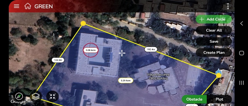
A confirmation message saying “Plot saved successfully” will appear on the screen.
You can now proceed to create a plan.
The Create Plan feature in AeroGCS GREEN helps you design drone mission plans suited to specific crop types and field conditions. This section provides a step-by-step guide for creating a plan, either by using a saved crop template or by setting up a new plan manually.
1. Starting the Plan Creation
- Tap on the Create Plan Button.
A confirmation dialog appears with the message:
“Do you want to use a saved crop template for planning?”
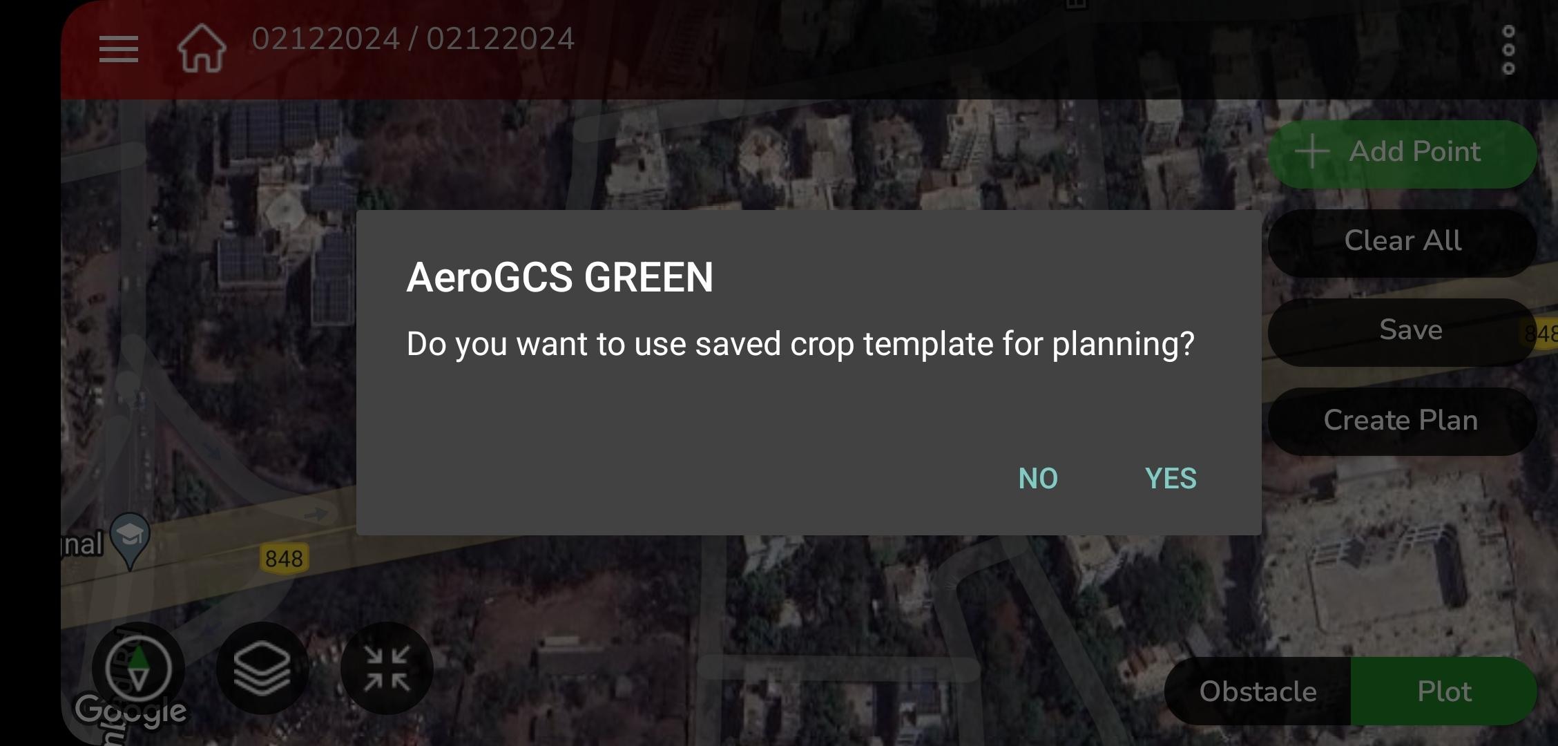
2. Choose Your Action:
- Tap Yes to use a saved crop template.
➔ This will take you to the Crop Template screen.
- Tap Yes to use a saved crop template.
- Tap No to manually set up the plan.
➔ This will take you directly to the Map View screen.
- Tap No to manually set up the plan.
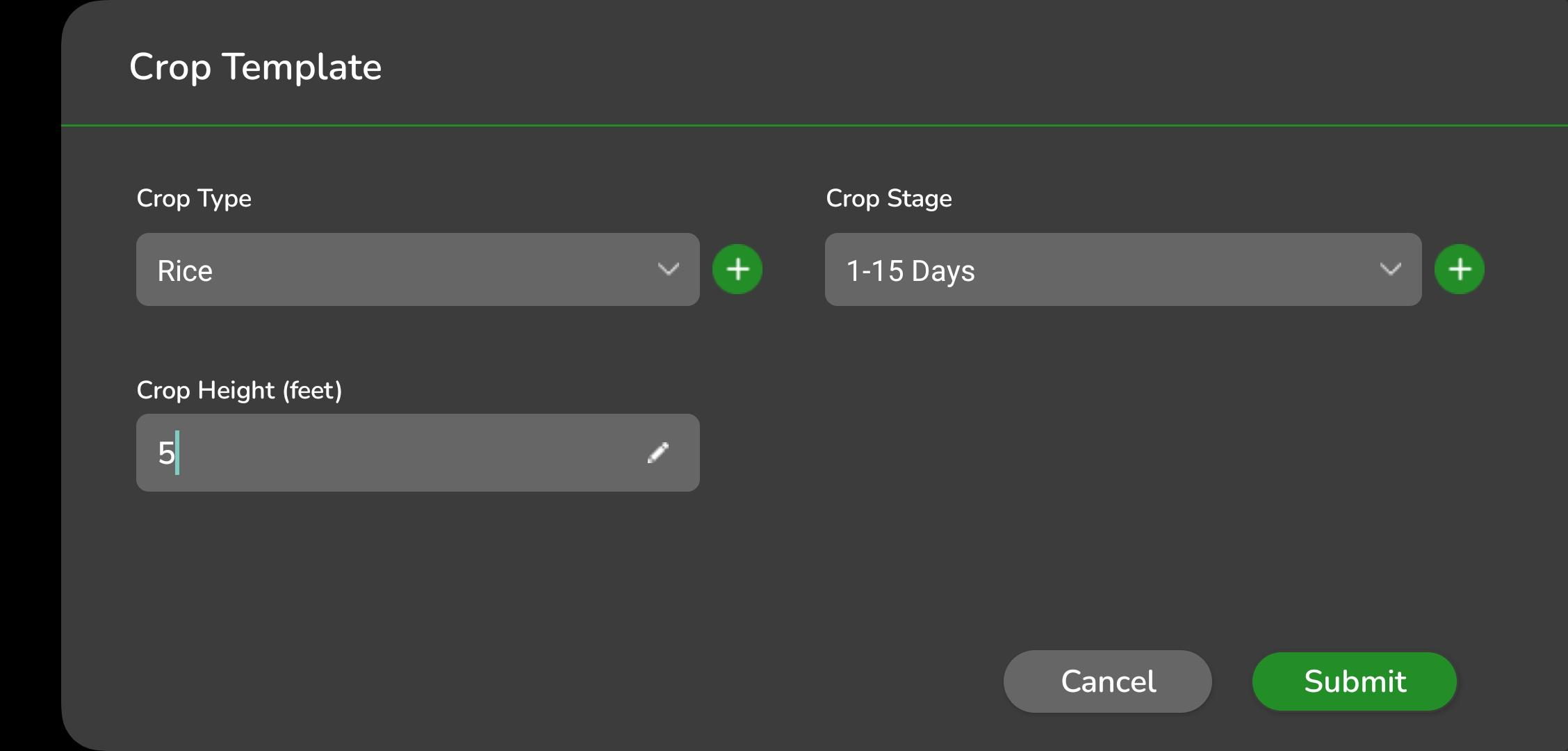
2. Using a Crop Template
If you choose Yes, follow the steps below to select or add crop details:

Step 1: Select or Add a Crop Type
- Select Crop Type from the drop-down list.
- If the required crop type is not available:
- Tap the + button next to the Select Crop field.
- In the Add Crop dialog:
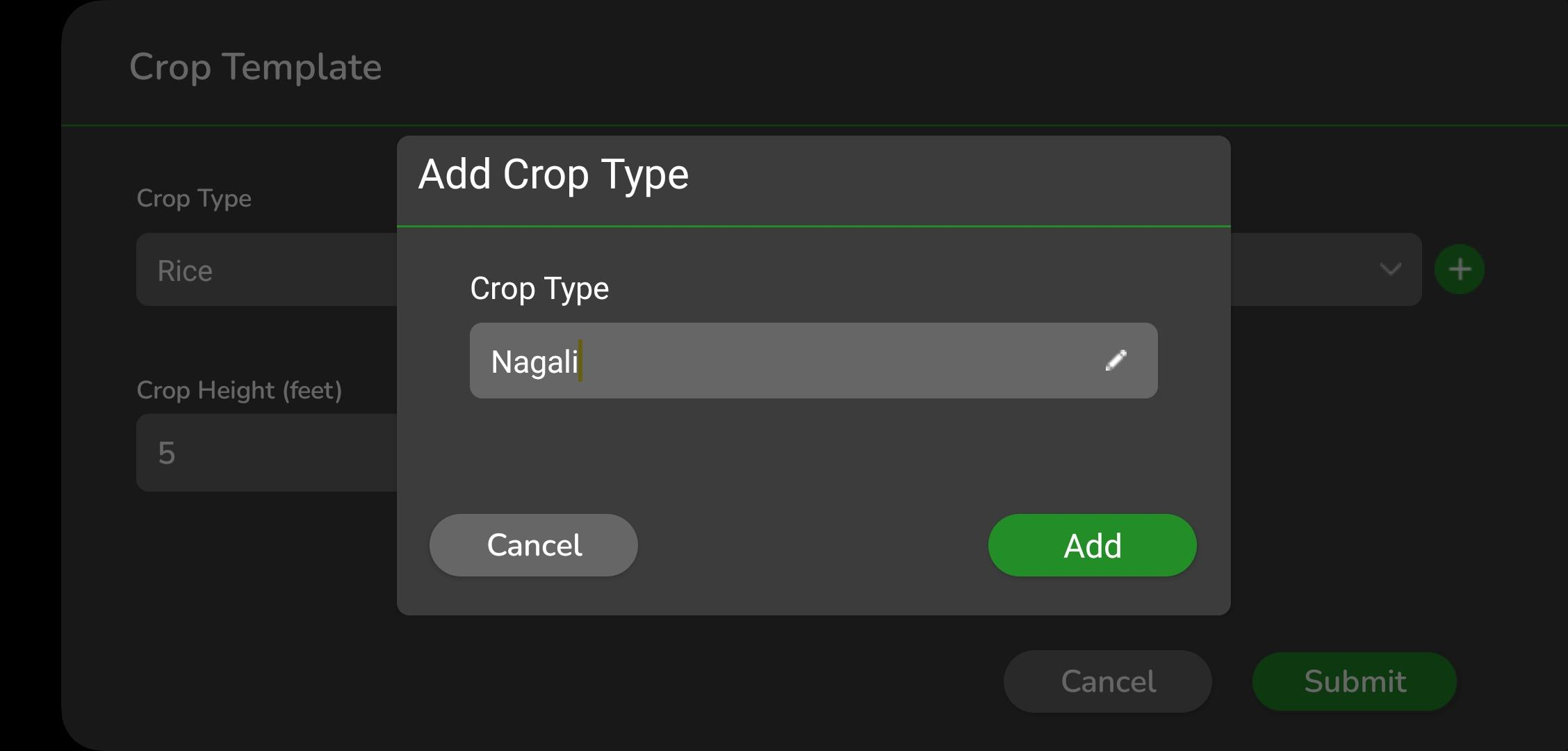
- Enter the crop name in the text field.
- Tap Add.
➔ The new crop type will now be available for selection.
Step 2: Select or Add a Crop Stage
- Select Crop Stage from the drop-down list.
- If the crop stage is not available:
- Tap the + button next to the Select Crop Stage field.
- In the Add Crop Stage dialog:
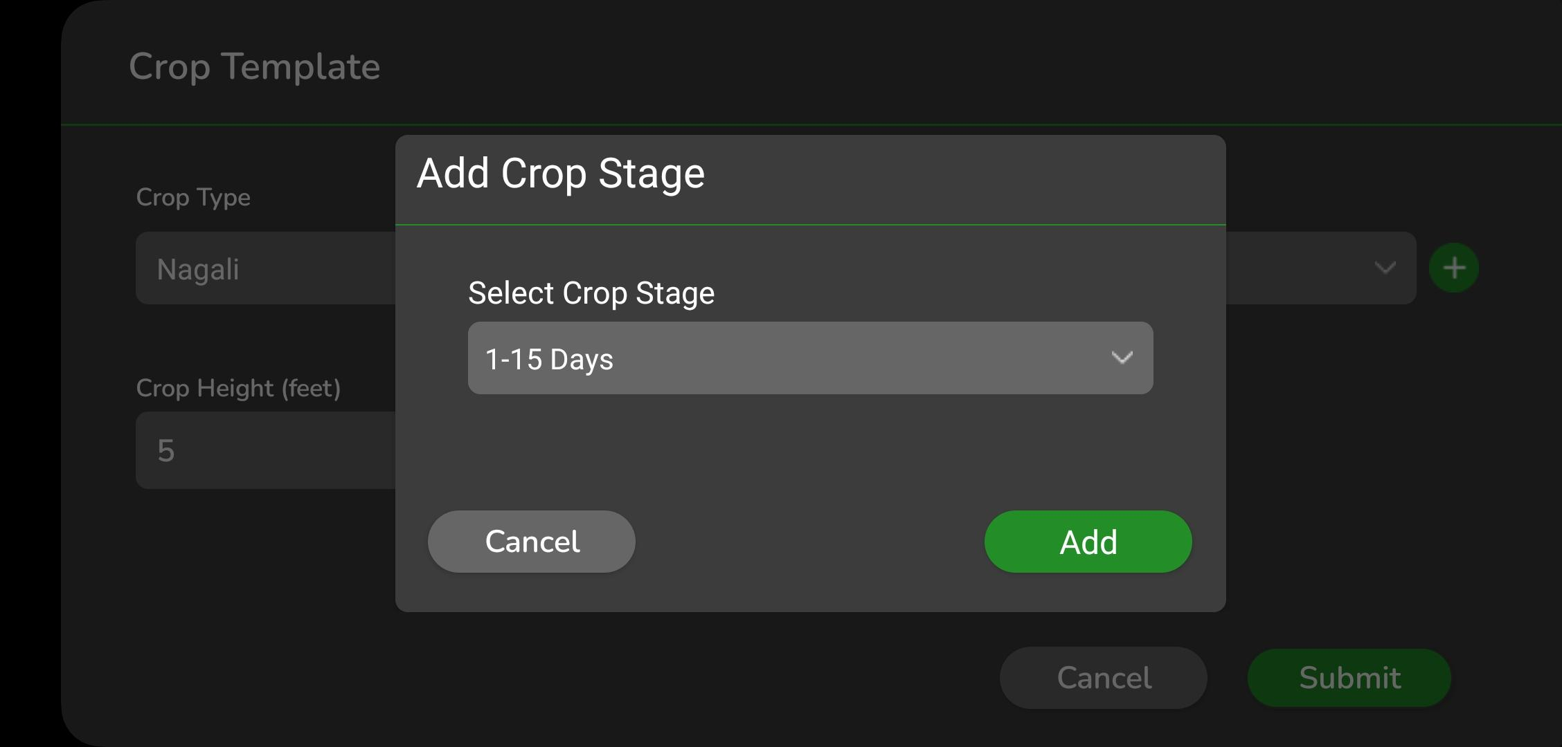
- Select the crop stage in days from the drop-down list.
- Tap Add.
➔ The new crop stage will now be available for selection.
Step 3: Enter Crop Height
- Enter the crop height in feet.
- Tap Submit to apply the crop template and proceed.
3. Completing the Plan Creation
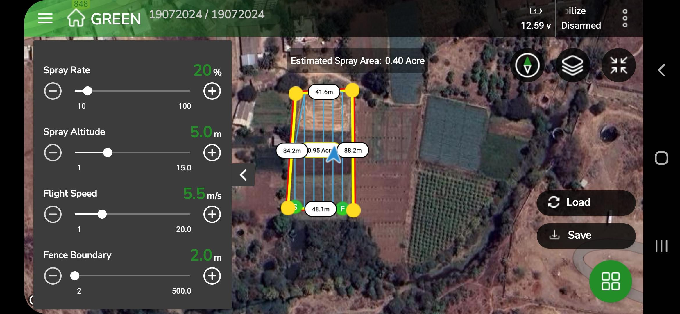
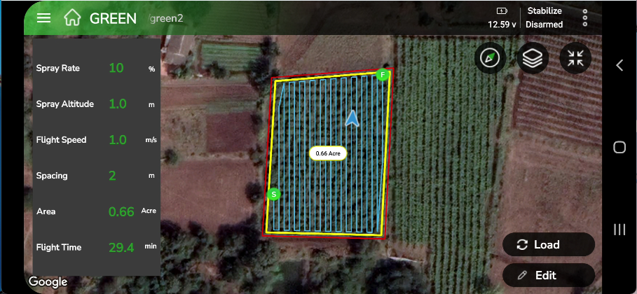
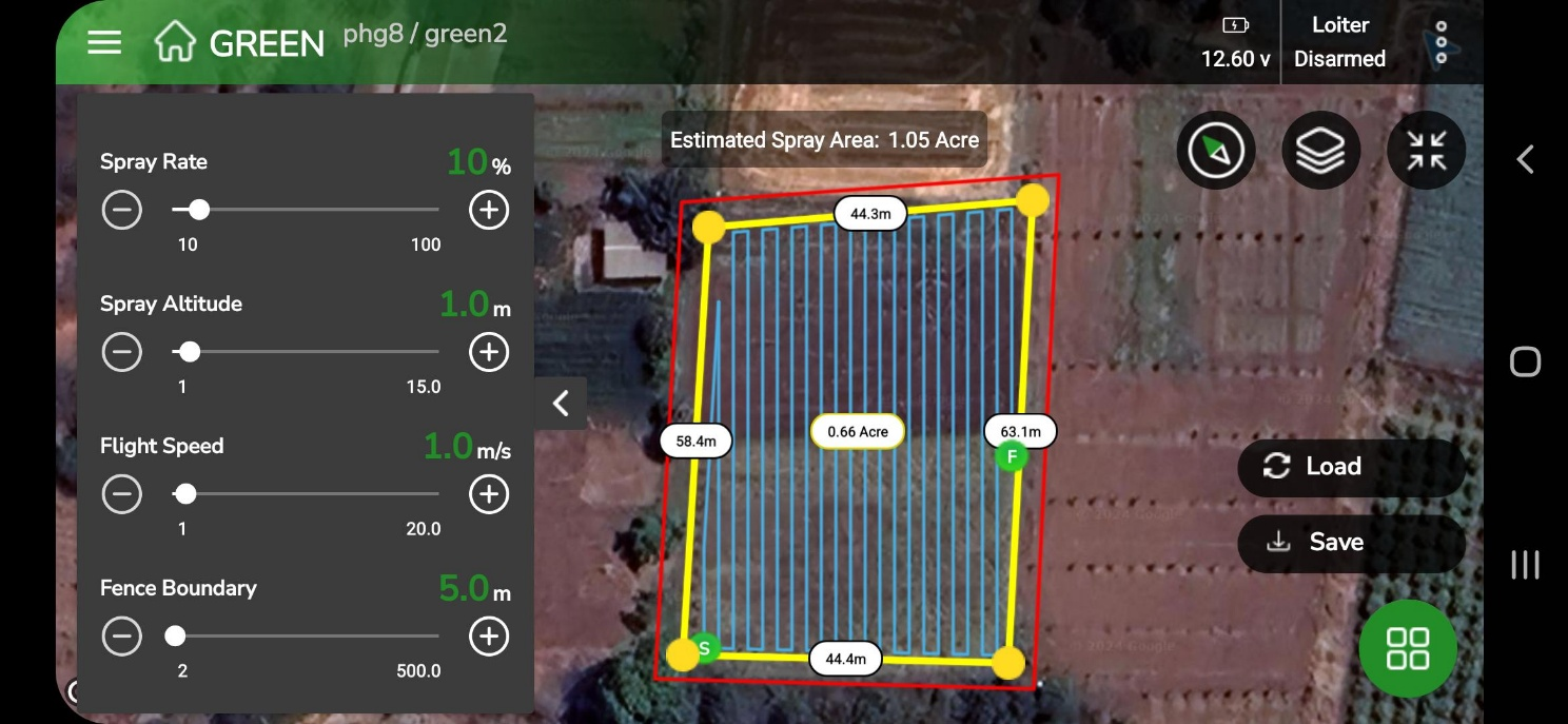
After submitting the crop template or selecting No to skip it, you will be directed to the Create Plan screen. This screen displays:
- Spraying Map: A map view showing the field layout and Boundaries.
- Parameter Settings Window: Let you adjust parameters for fine-tuning the mission.
Map View Details
- Field Dimensions
The map displays all plan dimensions, including lengths and area calculations in acres.
➔ The estimated spray area in acres is shown on the screen. - Editable Parameters
A list of parameters is available on the left-hand side of the screen.
➔ Use the slide bars to adjust values as needed. - Fence Boundaries
The field boundary is outlined in red, representing a virtual fence.
➔ You can customize this fence to suit your mission’s requirements.
Fence Boundary Features
The fence boundary serves two critical purposes:
- Prevention of Boundary Breaches:
If the vehicle approaches the boundary, a failsafe action (e.g., Return to Launch or RTL) is triggered to prevent it from leaving the designated area. - Obstacle Avoidance (for Copters in Loiter Mode):
When Object Avoidance is enabled, the vehicle will stop before crossing the boundary and may adjust its flight path to avoid the fence.
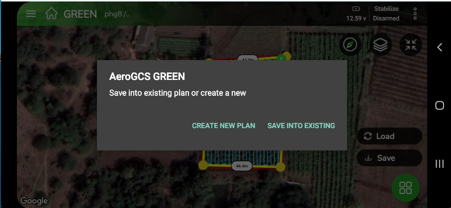
Step 1: Tap the Save button to save the plan in your project. A pop-up appears asking you to enter the Plan Name and confirm the Project Name.
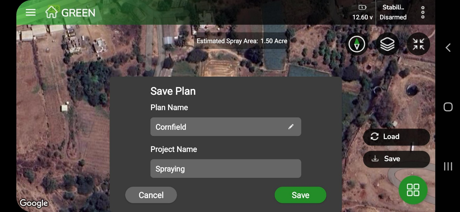
Step 2: Tap the green Save button to confirm. A message saying “Plan saved successfully” will appear at the bottom of your screen.
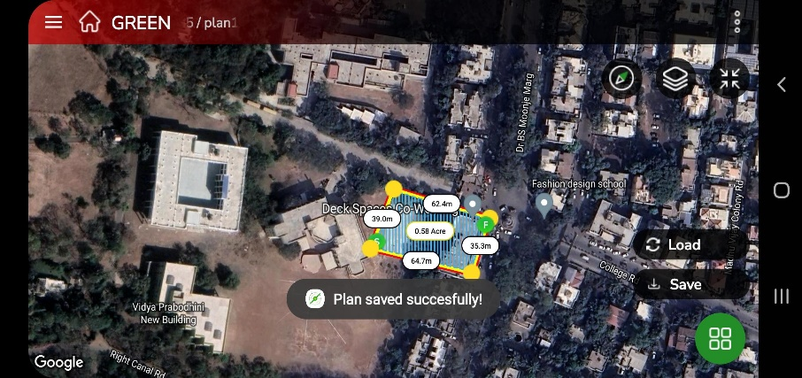
Save your plan with a clear name under the appropriate project. The saved plan will be stored in the same project and can be accessed whenever needed
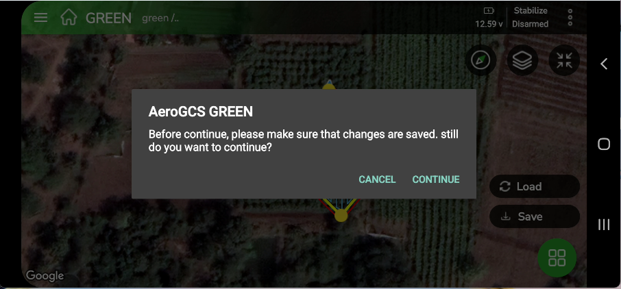
Step 3:
Tap Load to prepare the plan for flight. A confirmation message appears:
“Please make sure the changes are saved.”
You’ll see Cancel and Continue buttons.
5. Take Flight
Step 1: Tap the Arm/Fly button to start your flight. The Edit Parameter screen appears on your device
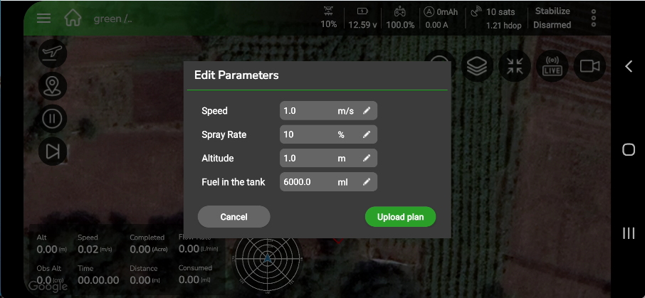
If needed, modify the parameters on this screen. Tap Upload Plan to upload your mission plan and proceed to flight prechecks.
After the precheck completes, tap OK to continue.
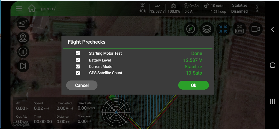
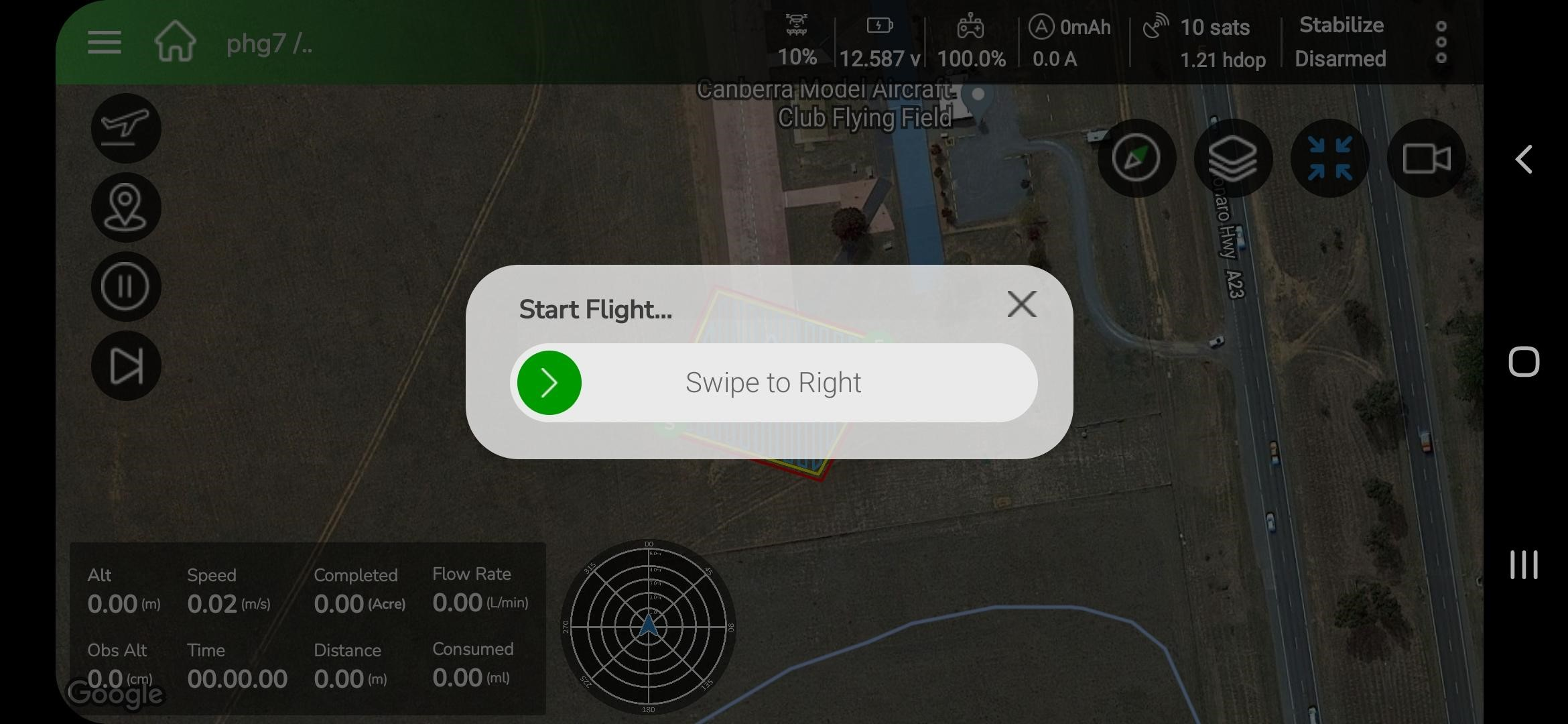
Slide the green arrow slider to the right begin the flight.
6.2.2 Manual Flying Method
1. Overview
The Manual Flying Method allows the pilot to operate the aircraft using the RC transmitter while monitoring live telemetry and controls on the Fly View screen. Three operational modes are available:
- MRef Mode (Manual Reference) — default mode displaying reference lines for guided manual flight.
- M-Manual Mode — full manual RC control without visual aids.
- AB Mode (A–B Reference Planning) — semi-automated mode for creating linear flight plans using two manually defined points.
Each mode is selectable from the Fly View screen after successful pre-check and arming.
2. Accessing Manual Flight
- When beginning a new mission, the application displays the Select Flying Method dialog with two options: Automatic and Manual.
- Tap Manual to proceed with manual operation.
3. The application loads the Manual Flight module and automatically initiates the pre-check sequence.
4. By default, the system enters MRef Mode
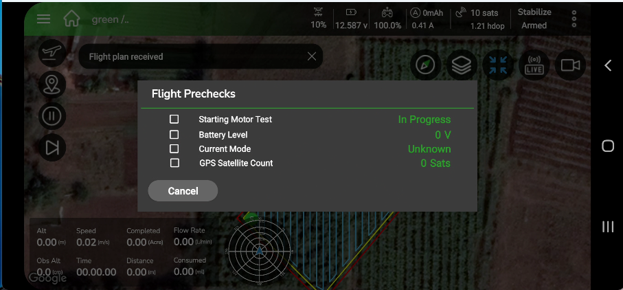
3. Pre-Check and Arming
- Tap Arm Motors to start the pre-check and arming process.
- The Flight Prechecks dialog lists:
- Battery Level
- Current Mode
- GPS Satellite Count
- Fuel in the tank (ml) (This Field is editable you can edit and enter correct new value)
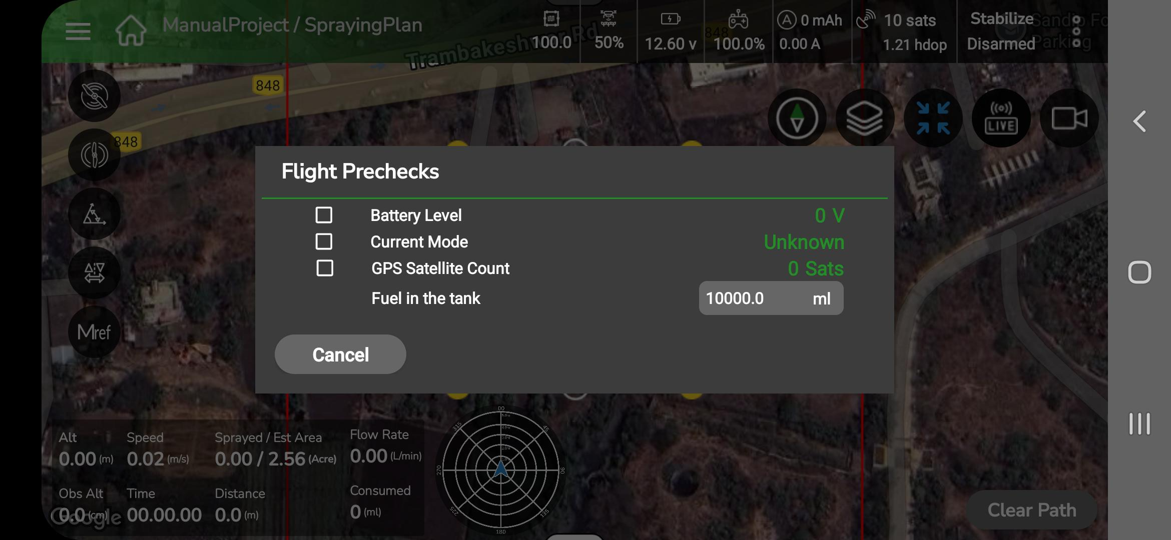
3. Verify each parameter. Tap Arm Motors when ready. On-screen messages will show: “Arming motors…” then “Pre-check completed successfully.”
4. If pre-check fails, follow the displayed guidance; arming is prevented until issues are resolved.
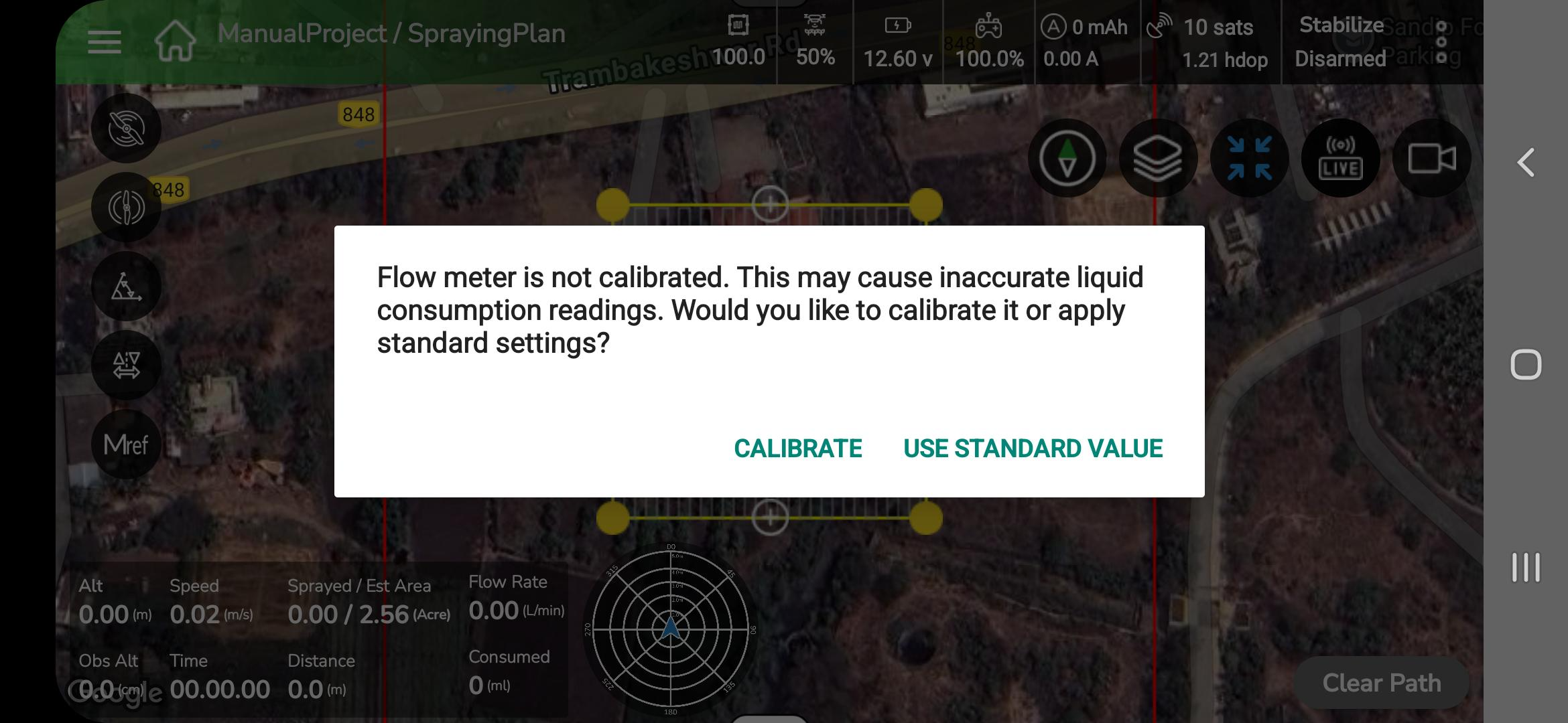
5. Flow meter calibration note: If the flow meter is not calibrated, a popup appears: “Flow meter is not calibrated. Calibrate / Use Standard Value.” Select the appropriate option before flight.
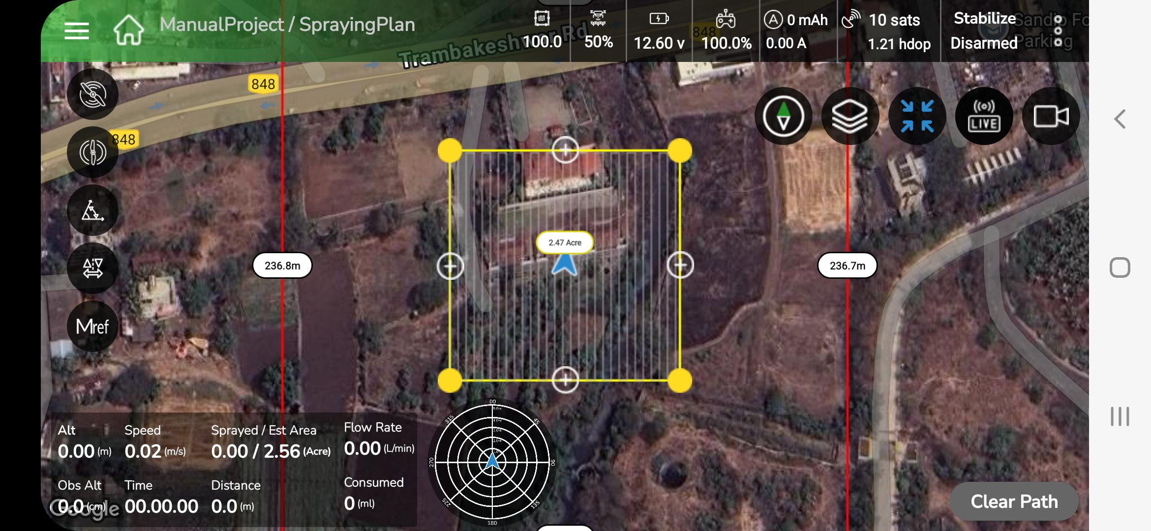
4. Fly View
- The Top Status Bar displays: Flight Mode, Connection Status, Battery, Altitude, GPS satellite count and HDOP.
- Telemetry Widgets display live speed, heading and other flight parameters.
- The map area shows a trace line indicating the drone’s live flight path.
5. Flight Mode Selection
- The Mode Selector appears on the Fly View control bar. Mode icons (MRef, M-Manual, AB) are circular buttons on the left-side panel; the active icon is highlighted.
2. Tap an icon to switch mode; voice confirmation follows (e.g., “Switched to M-Manual.”).
1. MRef Mode (Manual Reference)
- MRef is the default mode when entering Manual Flight. Reference lines (parallel/grid lines) appear on the Fly View map to guide the pilot for consistent passes.

3. Reference lines are visual aids only; the pilot retains full RC control.
2 M-Manual Mode (Full Manual)
- Selecting M-Manual removes reference lines and any visual assistance; the drone responds directly to RC stick inputs.
- Only core telemetry remains visible. Use this mode only in open, obstacle-free areas and when the pilot is experienced.
3 AB Mode (A–B Reference Planning)
The AB Mode enables the pilot to create a semi-automated spraying plan by defining two reference points Point A and Point B on the Fly View map.
The application then generates evenly spaced spray passes between these two points, aligned with the drone’s heading.
Steps to Use AB Mode
- Select AB Mode
- Tap AB Mode on the Fly View control bar.
- The AB Configuration Panel opens automatically on the left side of the screen.
- Configure the required parameters:
- Spray Altitude (m)
- Flight Speed (m/s)
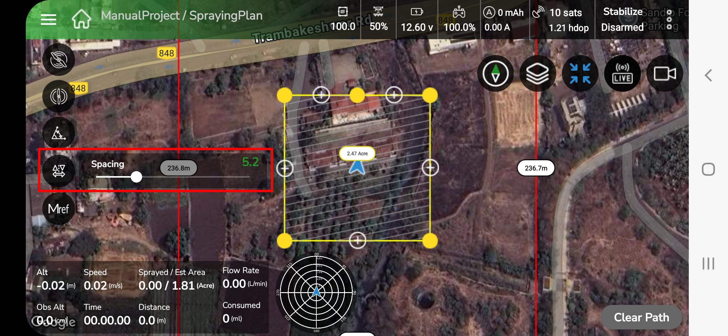
- Spacing (m)
- Mission Length (m)
- After configuring, tap the < (Back) button on the panel to close it and return to the Fly View map.
- The drone is now ready for marking Point A and Point B.
2. Mark Point A
- Fly the drone to the desired start position.
- Tap A on the screen to mark Point A.
- A green “A” marker appears on the map.
3. Mark Point B
- Fly to the next corner and align the drone along the desired spray direction.
- Tap B to mark Point B.
- Marker “B” appears, and the system automatically generates a plan of parallel blue spray lines between Points A and B, following the drone’s heading.
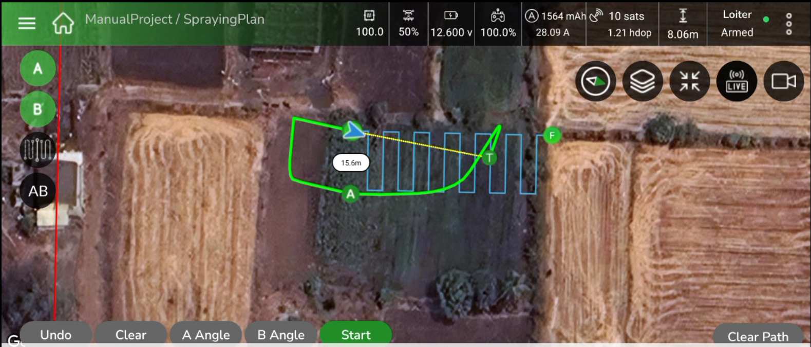
4. How the Plan Is Drawn
- The plan is generated along the recorded A–B heading.
- The number and spacing of lines are based on the configured Spacing (m) value.
- The plan fits within the visible mapped boundary of the field.
- The green path represents the drone’s actual or recent flight track.
5. Accessing the AB Toolbar
- Once the plan is created, the AB-specific toolbar appears at the bottom of the screen.
- It includes: A, B, Undo, Clear, A Angle, B Angle, Done, and Start buttons.
- These controls are used to refine the plan, adjust angles, and start the mission.
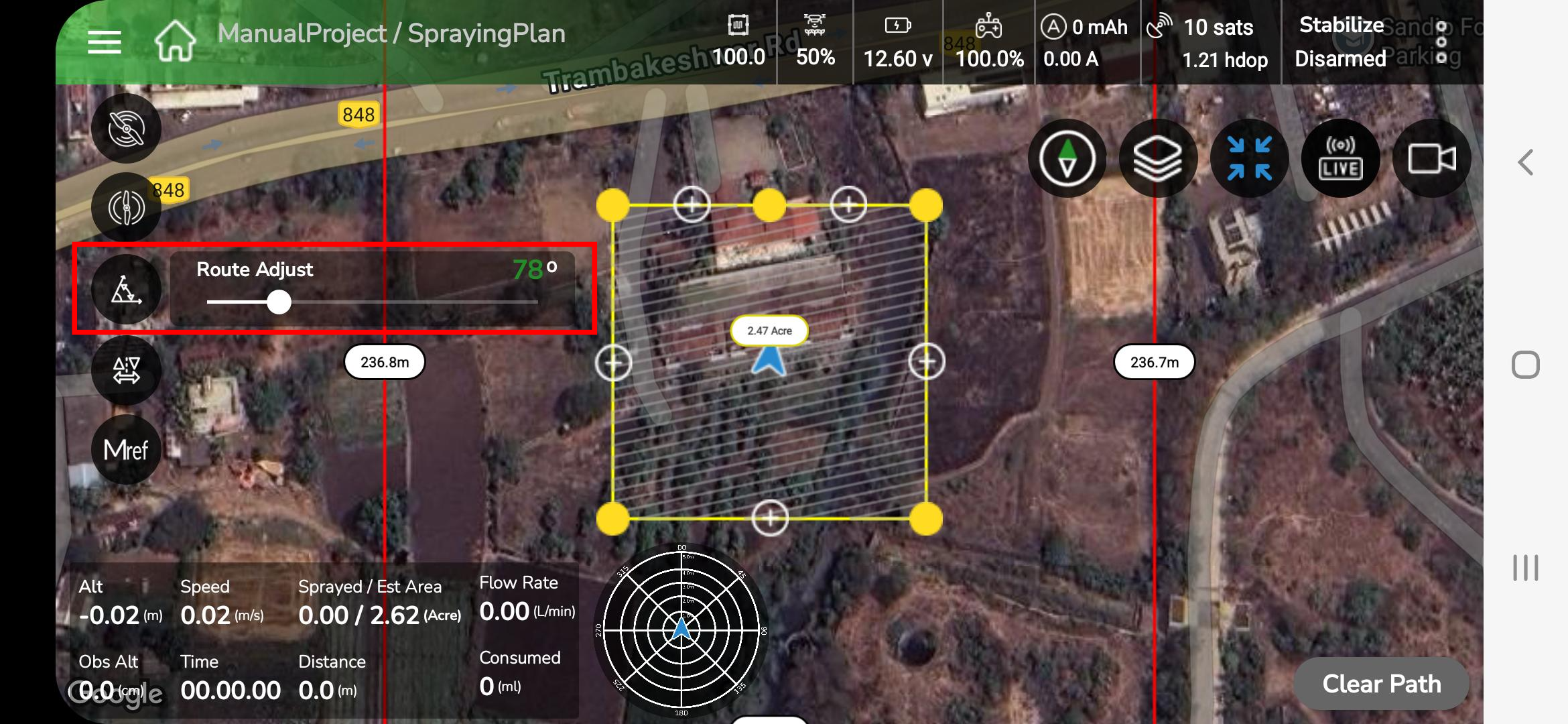
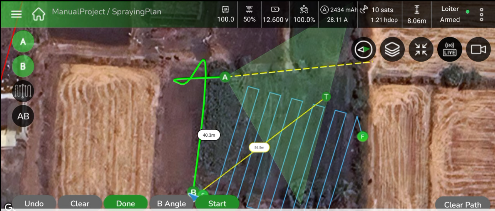
6. Adjusting Plan Angles
- Tap A Angle or B Angle to modify the plan orientation from either point.
- A triangular zone appears, showing the editable area for that corner.
- Rotating the drone heading updates the plan dynamically within this zone.
7. Undo and Clear Options
- Undo: Reverses the most recent change, such as an incorrect angle adjustment or point marking.
- Clear: Removes all markers and lines to redraw the plan.
- Clear Path: Deletes only the currently drawn plan; the drone continues flying manually.
8. Finalize the Plan
- After adjusting A/B angles and spacing, tap Done to finalize and lock the plan layout.
- The plan is now ready for execution.
9. Confirm and Start the Plan
- Tap Start to confirm and load the finalized plan.
- The Mission Settings Panel reappears for final verification.
- Review the altitude, speed, spacing, and mission length.
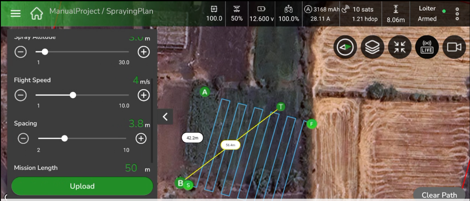
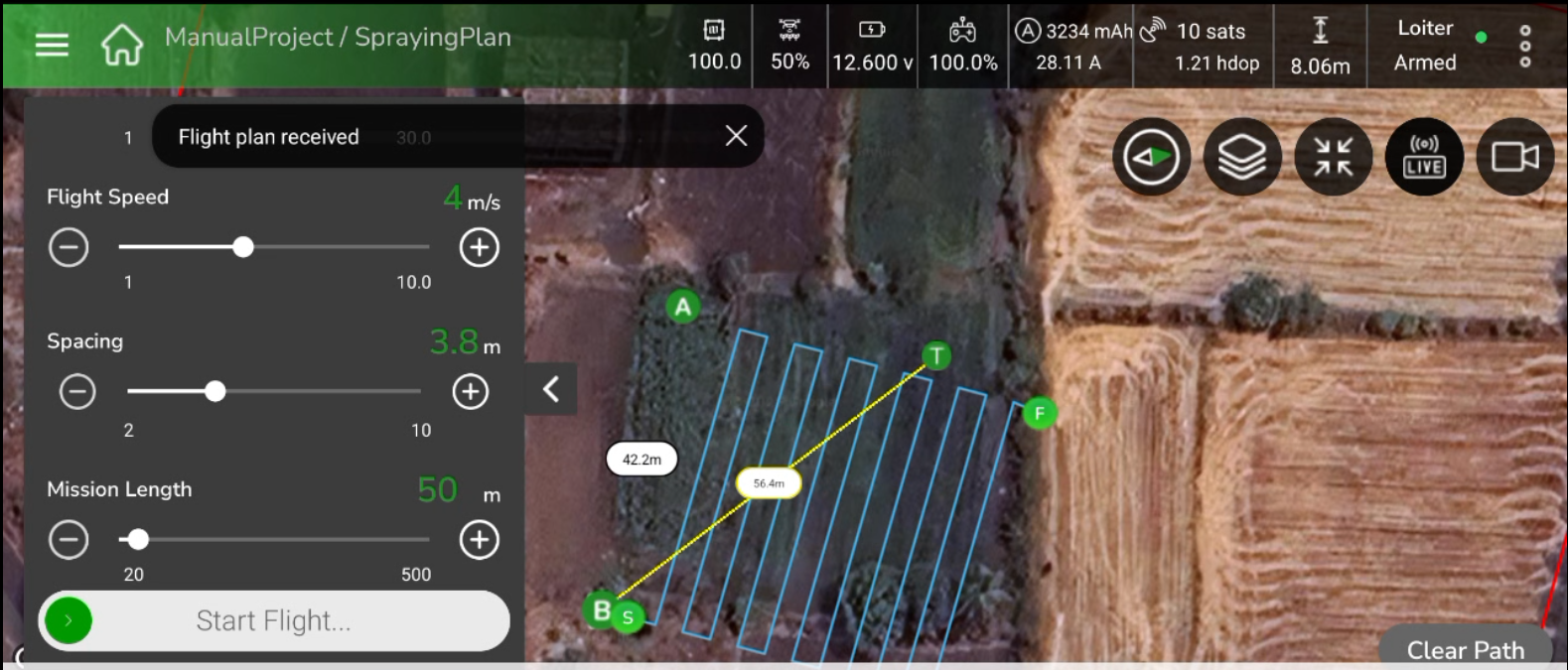
10. Upload the Mission
- Tap Upload to send the mission plan to the drone.
- The application displays status messages sequentially:
“Uploading…” → “Flight plan received.” - Once upload is complete, the Start Flight button becomes active.
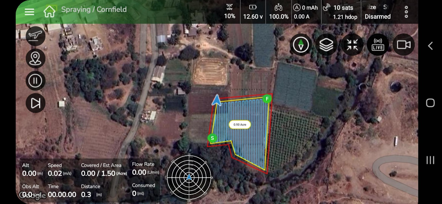
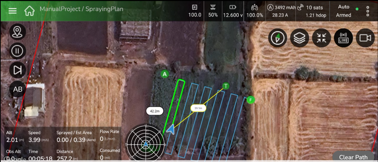
11. Start Flight and Execution
- Swipe > Start Flight to begin spraying along the generated passes.
- The drone automatically follows the plan lines while maintaining altitude, speed, and spray rate.
- Live telemetry (altitude, speed, sprayed area, flow rate, and time) displays at the bottom.
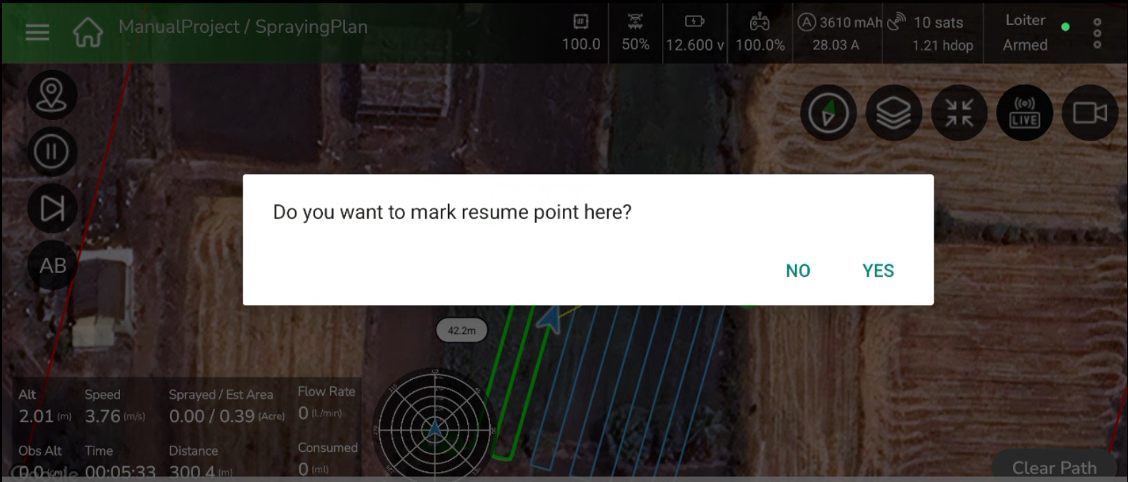
12. Resume Function (During Spraying)
- If the operation is paused or interrupted, a prompt appears:
“Do you want to mark resume point here?” - Tap Yes to mark the resume point.
- When resumed, the drone continues spraying from that exact position.
- If the operation is paused or interrupted, a prompt appears:
13. System Feedback and Alerts
- If an invalid rotation or angle is applied, a message appears:
“B point angle is not allowed.” - Correct the heading and adjust within the valid range before continuing.
- If an invalid rotation or angle is applied, a message appears:
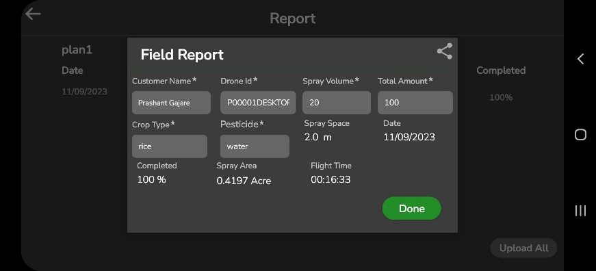
14. Post-Spraying Report and Acreage Summary
- After the spraying task completes, the Field Report window opens automatically.
- The report displays details such as Area Covered, Spray Volume, Sprayed Area, Plot Area, Flight Time, and Applied Agrochemical.
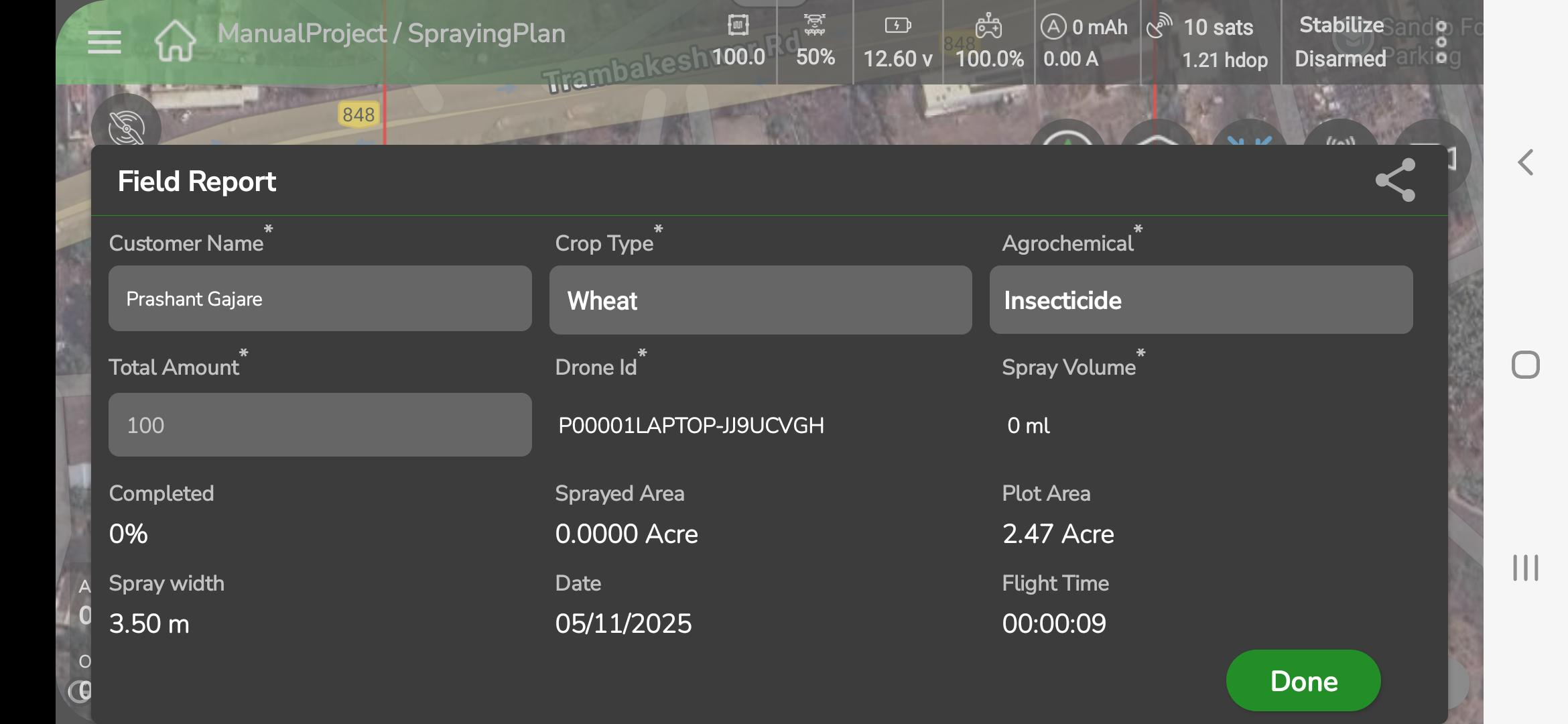
- Review or edit details as required and tap Done to save.
- Once saved, the data syncs automatically with AeroGCS Enterprise (if logged in), and a message “Report saved successfully” appears.
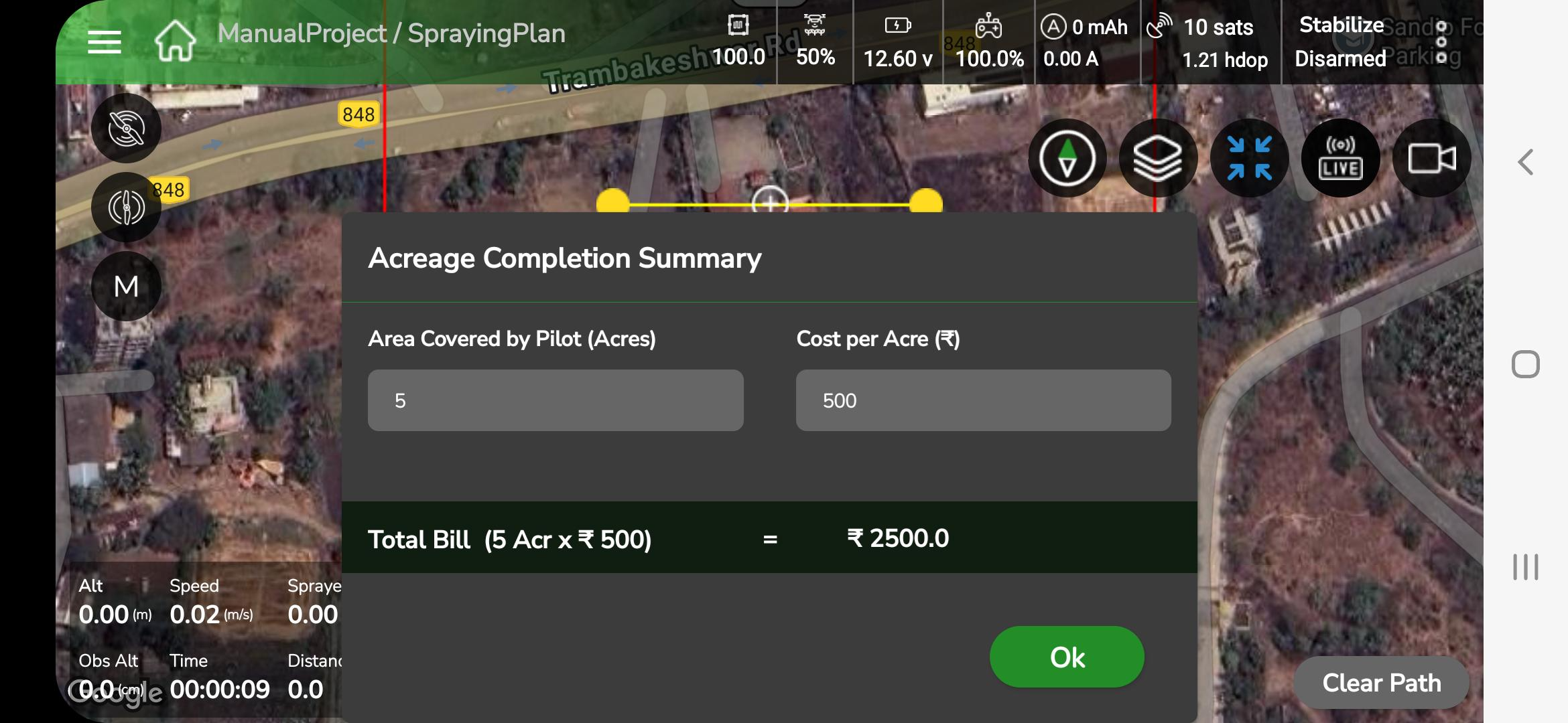
- The Acreage Completion Summary window then opens, displaying:
- Area Covered by Pilot (Acre)
- Cost per Acre (₹)
- Total Bill automatically calculated (e.g., 5 Acre × ₹500 = ₹2500)
- Review the information and tap OK to confirm completion.
- The mission closes and returns to the Fly View screen.
| Control | Function | Description |
| Arm Motors | Arm | Initiates motors after successful pre-check |
| Mode Selector | Mode Switch | Switch between MRef, M-Manual, AB Mode |
| Fence Icon | Fence Settings | Open slider to set outer/inner fence radii |
| Set A / Set B | Point Marking | Record A and B for plan generation |
| Mirror | Plan Flip | Mirror the plan to the opposite side of A–B |
| Clear Path | Clear Plan | Removes current plan; flight continues |
| Pause / RTL | Return to Launch | Command drone to return and land |
| Disarm | Motor Stop | Disarm motors after landing |
| Save / Apply | Save | Save plan or field report |
- Tap Fence Icon to open the fence slider.
- Adjust outer fence distance (2 m to 30 m). Maximum fence limit defaults to 500 m (OEM default) — confirm OEM setting if different.
- Modify inner fence by dragging yellow waypoints on the map.
- When the drone approaches the outer fence the app shows a popup “Fence limit approaching” and a voice alert “Fence limit.” If the fence is breached, the configured failsafe (Hover / RTL / Land) is executed.
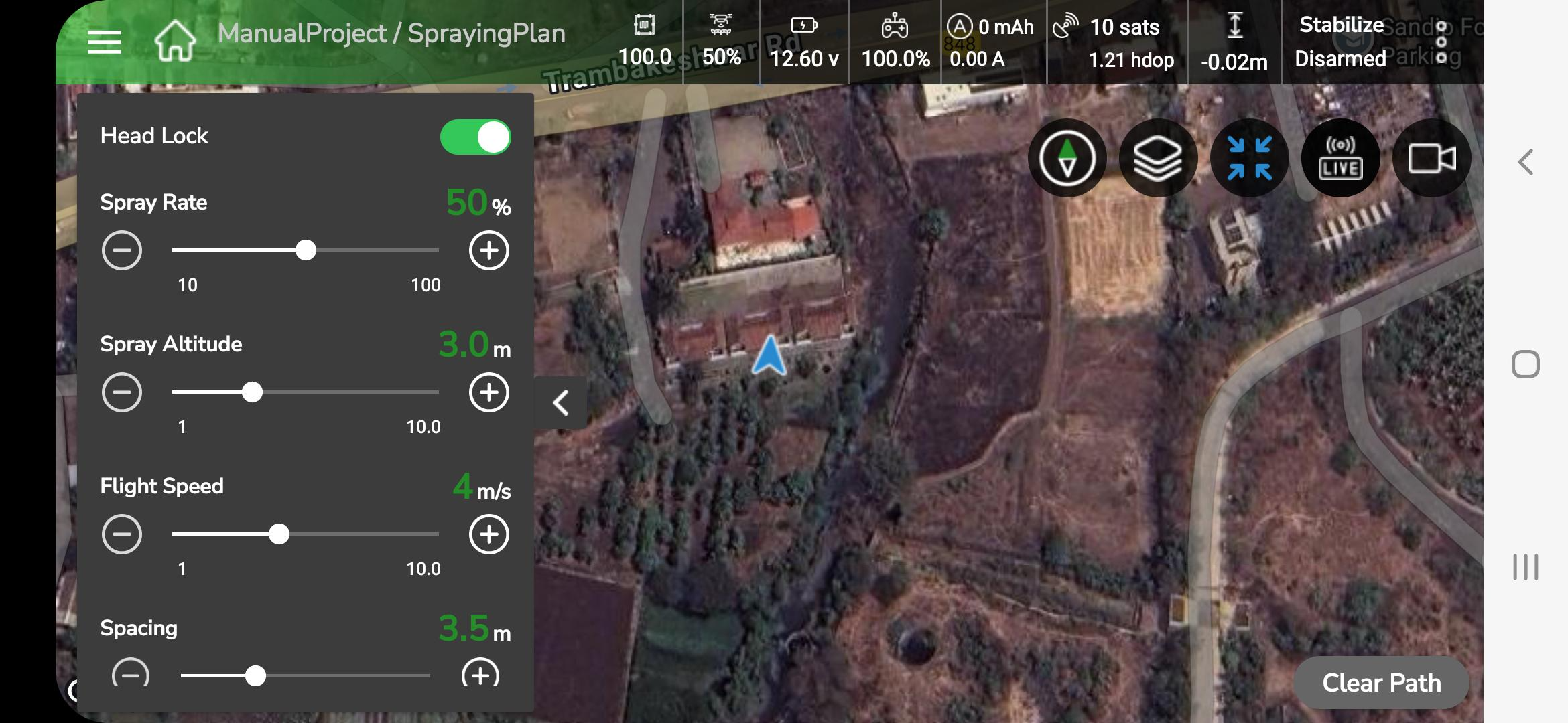
1. The left-side parameter panel provides the following controls:
- Head Lock: toggle to maintain heading.
- Spray Rate (%) — adjust liquid output.
- Spray Altitude (m) — set operation altitude.
- Flight Speed (m/s) — set ground speed.
- Spacing (m) — set distance between passes.
- Changes apply immediately; voice feedback confirms updates (for example, “Altitude five meters.”).
- Tap Pause / RTL to command automatic return. The system calculates and executes a safe RTL path.
- Announcements: “Returning to launch.” followed by “Landing initiated.”
- After touchdown the aircraft disarms; on-screen message “Drone disarmed successfully.”
1. Field Report
- After disarm the Field Report window opens automatically.
- Enter required details (Spray Area, Duration, Remarks).
- Tap Done to save. The app shows “Report saved successfully.”
2. Sync
- If AeroGCS Enterprise login is active, the app begins automatic sync. A progress bar with percentage displays during upload.
- Voice/toast messages: “Syncing report to Enterprise.” → “Sync completed.”
- The dashboard reloads and voice announces “Mission completed.” Mission logs (telemetry, battery, timestamps) are recorded automatically.
3 Acreage Completion
- After report submission, the Acreage Completion Summary is displayed showing: Area Covered (Acre), Cost per Acre (₹), and Total Bill.
- Review displayed values and tap OK to finalize.
| Mode | Description | Automation level | Visual aids | Typical use |
| MRef | Manual flight with reference lines | Semi-guided | Reference lines, spacing & angle controls | Precision spraying / pattern flight |
| M-Manual | Full RC manual control | Fully manual | None | Advanced manual flying |
| AB Mode | A–B based plan generation | Semi-automated | Plan lines, Mirror, Yellow triangle | Strip/linear spraying |
- Verify GPS lock and battery before arming; recommended battery ≥ 95% for full missions.
- Use M-Manual Mode only when sufficiently trained and within visual line-of-sight.
- Clear Path clears the visible plan but does not pause or disarm flight; maintain RC control after clearing.
- In AB Mode, verify heading at Point B and plan mirror orientation before commencing spraying.
- Ensure reports sync successfully before exiting the session.
- Comply with local UAV regulations and always maintain safe altitude.
6.3 Handling Existing Project
AeroGCS GREEN allows you to use existing projects to make your work easier and more organized.
You can efficiently manage your projects using the app’s simple and clear interface. This section guides you through accessing, editing, renaming, and deleting projects and their related plans or plots. Managing existing projects helps you maintain smooth and flexible drone operations while saving time in the field.
6.3.1 Open existing project
A project acts as a container that stores all related plans and plots together. When you select a project, the screen displays a list of all the available plans and plots contained within it.
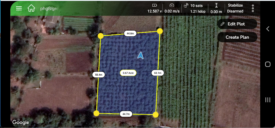
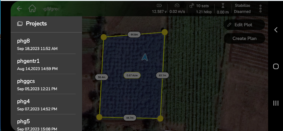
Step 1: To access existing projects, open the Home Menu. From there, select and tap the project you want to open from the list displayed on the screen, as shown below.
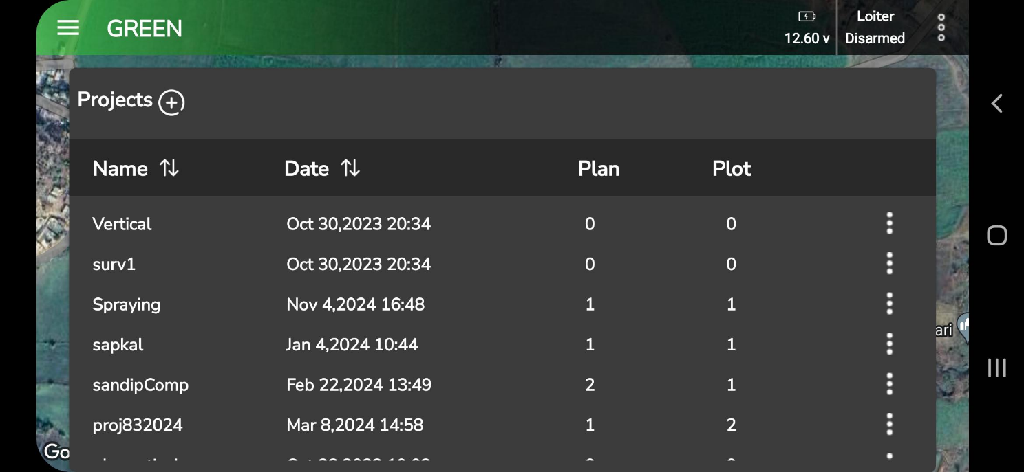
Step 2: Tap the project name to view its details, as displayed in the following screen.
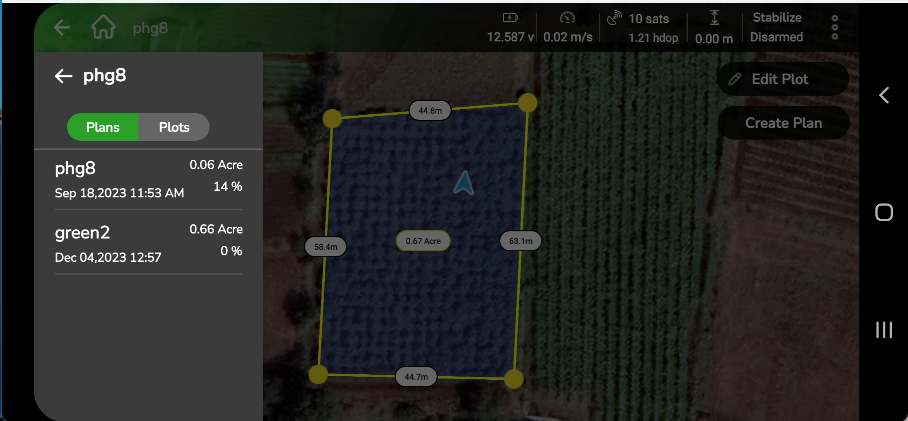
Each project can contain multiple plans and plots. To view either list, use the Plan/Plot toggle button. Depending on your selection, the app will display the corresponding list.
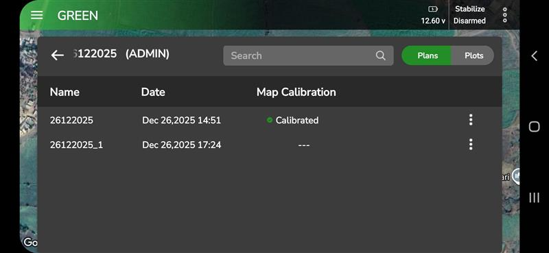
Map Calibration Status (Plan / Plot List)
In the Plan and Plot list view, AeroGCS GREEN displays a Map Calibration column indicating the calibration state of each plan or plot.
- Calibrated – Created after map calibration was performed.
- — – Created before map calibration or without calibration.
This column is display-only. Calibrated and non-calibrated plans or plots can appear together in the same project. The status is stored with the plan or plot and remains visible after restarting the application.
If you want to find a specific plan or plot, use the Search feature shown in the screen. To open a particular plan or plot, simply tap its name.
The Plan View appears as shown below.
The Plot View appears as shown below.
Step 2: Select the project you want to open. This will display all the plans and plots within that project. Use the toggle button to switch between plans and plots. The respective list will appear as shown in the following screens.
6.3.2. Edit a Plan
To make changes to an existing plan, open the plan screen and tap the Edit button to modify it.
On the left-hand side of the screen, you will find a list of parameters that can be adjusted using slide bars. You can control the following parameters:
- Spray Rate: Adjust the spraying rate from 10% to 100% using the slide bar.
- Spray Altitude: Set the spraying altitude between 1 meter and 15 meters.
- Flight Speed: Adjust the flight speed within the range of 1 m/s to 20 m/s.
- Fence Boundary: Set the fence boundary between 2 meters and 500 meters.
Once you’ve made the required adjustments, you can either save the changes to the existing plan or create a new plan within the same project to store these updates.
If the flight has not been completed and contains a marked resume point, editing the parameters will remove the resume point. You can use the slide bars on the left-hand side to modify the parameters as needed.
You can also use the settings icon to fine-tune parameters, adjust routes, and make other plan modifications.
The screen showing these parameters appears as shown below.
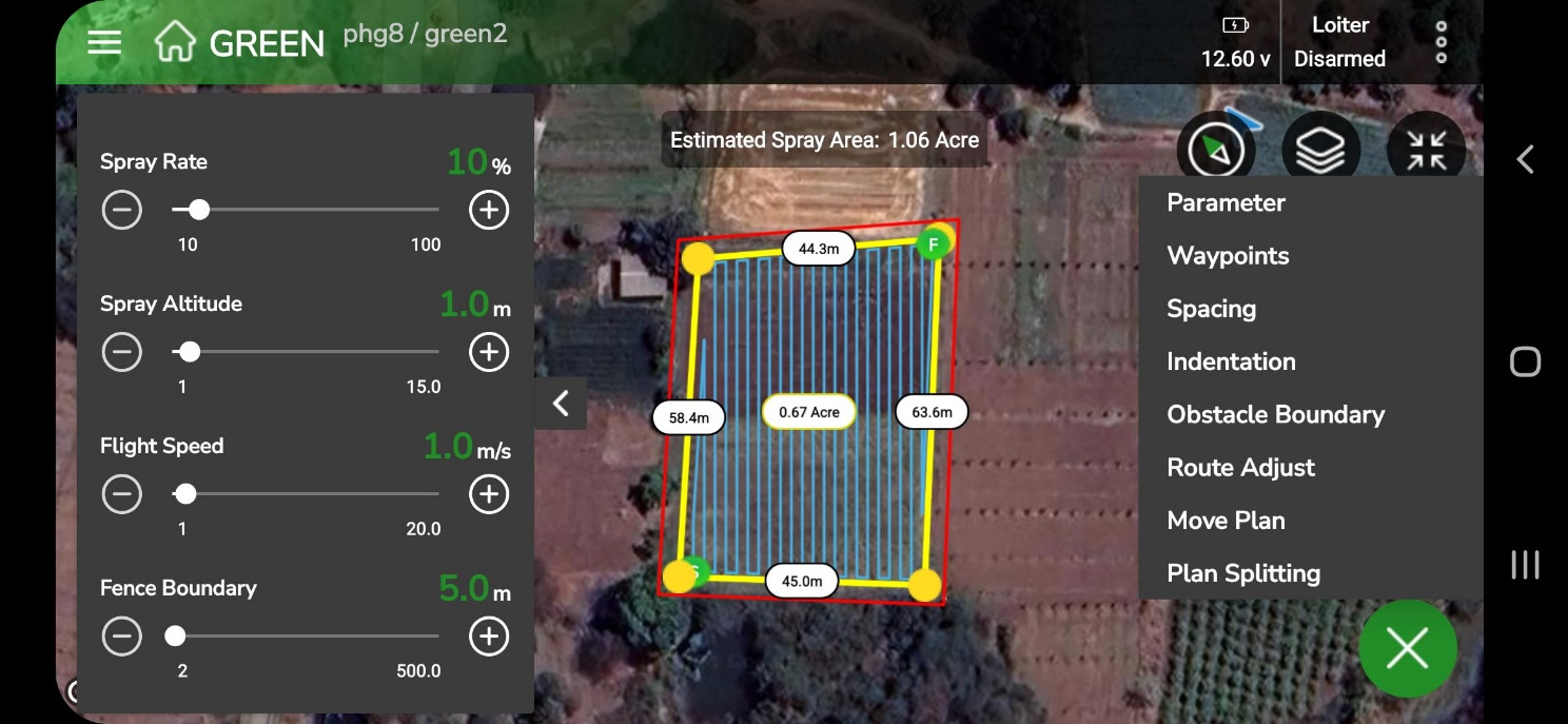
This section provides access to the following settings:
- Parameters
- Waypoints
- Spacing
- Indentation
- Obstacle Boundary
- Route Adjust
- Move Plan
- Plan Splitting
For detailed information about these options, refer to the Mission Planning Functionality section of this manual.
After making all necessary adjustments, save your changes and tap Load to initiate the flight. Observe the flight with the updated parameters, complete the mission, and generate a report. Any recent changes made to the plan or plot will be saved and displayed in the list for your reference.
6.3.3 View and Edit the Plan Report
You can view and edit an existing report for any selected plan. To open the report, go to the following screen.
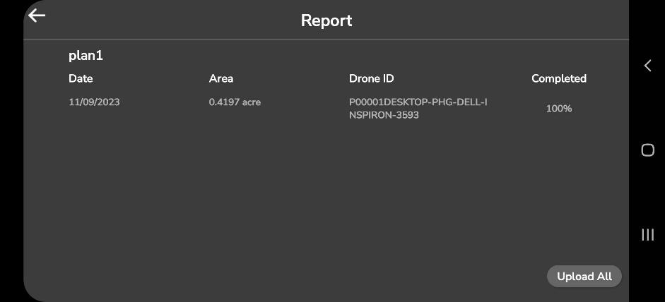
To edit the report, tap the row containing the report details. This will open the Field Report Generation view, as illustrated in the following screen:
Update the required fields with the new values and tap Done to save the changes.
| Note: If your device is offline or experiencing a slow internet connection, the field report may not upload automatically. In such cases, an “Upload” button will appear on the field report screen, allowing you to manually upload the report once a stable internet connection is available. |
6.3.4. Edit a plot
Similar to plan editing, you can also edit any plot saved within a project. This feature allows you to modify a plot directly on the map. Select the plot you want to edit from the list and follow the steps below.
To make changes to an existing plot, open the following screen and tap the Edit button.
After tapping Edit Plot, you will be prompted to select the method for editing the field plot. The available options will appear on the following screen.
To edit a field plot, choose one of the following methods by tapping on it:
- RC/Mobile
- Drone
- Map
Once you select a method, the plot editing screen will open, allowing you to modify the plot using the selected option.
On this screen, you can view and adjust the field plot before performing field operations. The map view displays a satellite image of the field with the plot area outlined in yellow. You can use the following options to make changes:
- Add Point: Tap to add more waypoints and refine the plot boundaries.
- Clear All: Remove all waypoints and obstacles. A confirmation message will appear before clearing.
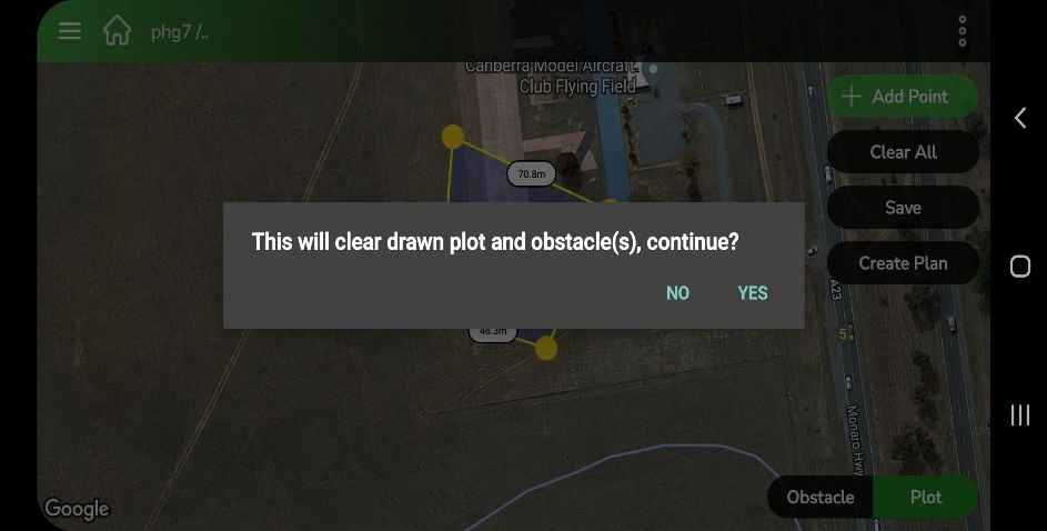
- Save: Tap Save to store the current plot configuration.
- Create Plan: Tap Create Plan to move to the plan creation stage for field operations.
The Obstacle and Plot toggles provide additional options for marking obstacles or switching back to plot-editing mode. The top status bar shows real-time metrics, helping you monitor conditions for safe and accurate field operations.
This feature lets you modify or add obstacles to an existing plot if required. Follow the on-screen prompts for guidance. Once you’ve made the necessary changes, tap Save Obs to save the obstacle to your plot:
Step 1: Open the Obstacle screen from the plot view, as shown below.
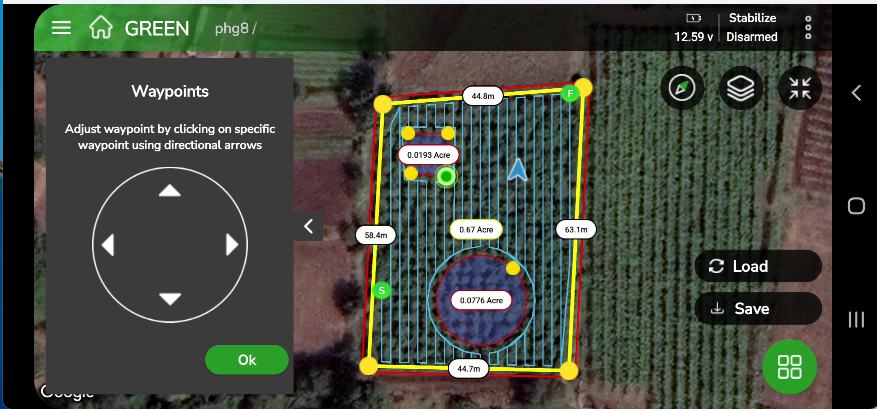
To edit a Polygon type obstacle:
- Select the waypoint you want to modify. It will turn green.
- Use the Waypoint Editor widget to move the waypoint using the small arrows in the east, west, north, or south direction.
- After adjusting, tap OK to confirm.
To delete a selected waypoint, tap the waypoint and then tap the Delete button in the Waypoint Widget.
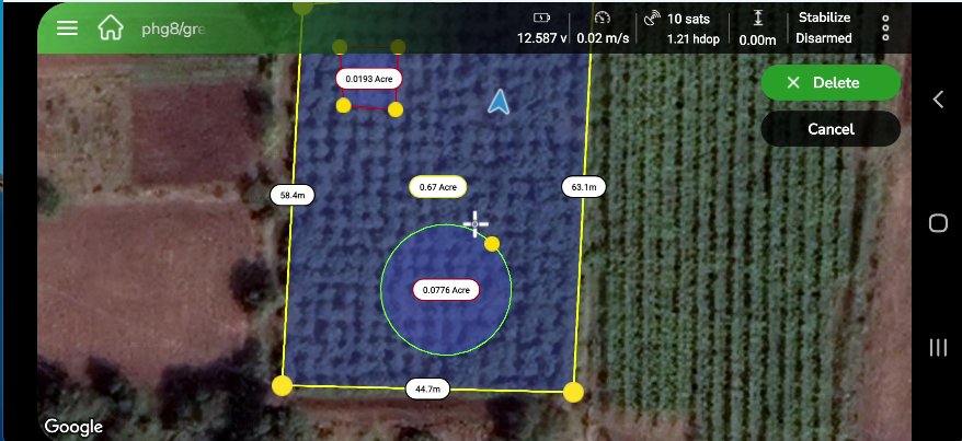
To edit a Circle type obstacle:
- Select a point on the edge of the circle.
- Drag the point inward to reduce the obstacle’s size or outward to expand it.
- Tap OK once your changes are complete.
When you’ve finished editing the plot, tap Save to store all updates.
To delete an obstacle from a plot, tap on the edge of the obstacle. It will be marked for deletion (the edge turns green), and a Delete button will appear, as shown below.
| Note: Deleting obstacles is not possible from the Plan View. To remove an obstacle, please switch to the Plot View. |
After saving the edited plot, you can create a mission plan by following the steps provided in the Creating a Plan section.
6.3.5 Add a plot to the existing project
AeroGCS GREEN allows you to easily add new plots to an existing project, helping you keep all related plots organized under a single project. This approach improves efficiency and ensures better management of your drone operations.
Follow the steps below to add a new plot to an existing project in AeroGCS GREEN:
Step 1: Navigate to the Target Project
- On your AeroGCS GREEN dashboard, locate the project where you want to add a new plot.
- Tap the project to open it.
Step 2: Access the Plots Section
- Inside the opened project, tap the Plots button to open the plots screen.
Step 3: View Existing Plots
- The plots screen displays a complete list of all plots currently linked to the selected project.
Step 4: Start Creating a New Plot
- Tap the + button on the plots screen. This icon is used to create a new plot.
- Tap + to begin.
Step 5: Begin the Plot Creation Process
- After tapping +, you’ll be redirected to the main AeroGCS GREEN screen.
- Tap Start Here to begin the plot creation process. The app will guide you through the same steps described in the Create a Plot section of this manual.
By following these steps, you can quickly add a new plot to any existing project in AeroGCS GREEN, keeping your project workspace organized and easy to manage.
6.3.6 Download Plot and Plan
You can download plans and plots for projects that are synchronized from AeroGCS Enterprise to AeroGCS GREEN when you are logged in to your account.
Scenario
- You are logged in to your AeroGCS Enterprise account through AeroGCS GREEN.
- Projects are automatically synced from AeroGCS Enterprise to your AeroGCS GREEN dashboard.
- However, not all plans and plots are downloaded automatically with the project.
Follow the steps below to manually download plans or plots.
How to Download Plans and Plots
Step 1: Open the Project
- Locate the project for which you want to download plans or plots from your AeroGCS GREEN
- Tap the project to open it.
Step 2: Navigate to the Plots/Plans Tab
- Inside the project, open the Plots or Plans tab, depending on what you want to download.
Step 3: Select Plan or Plot
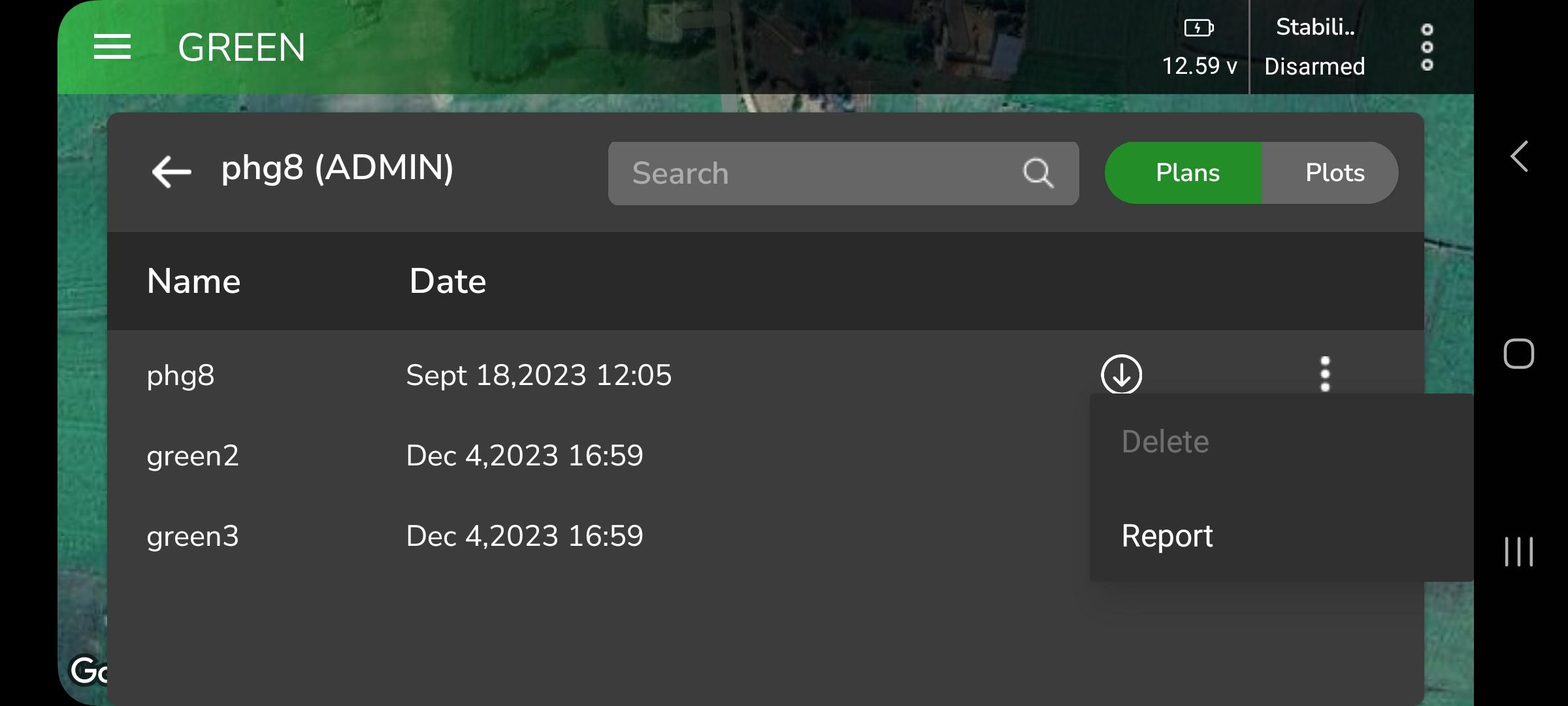
- From the list, identify the specific plan or plot you want to download.
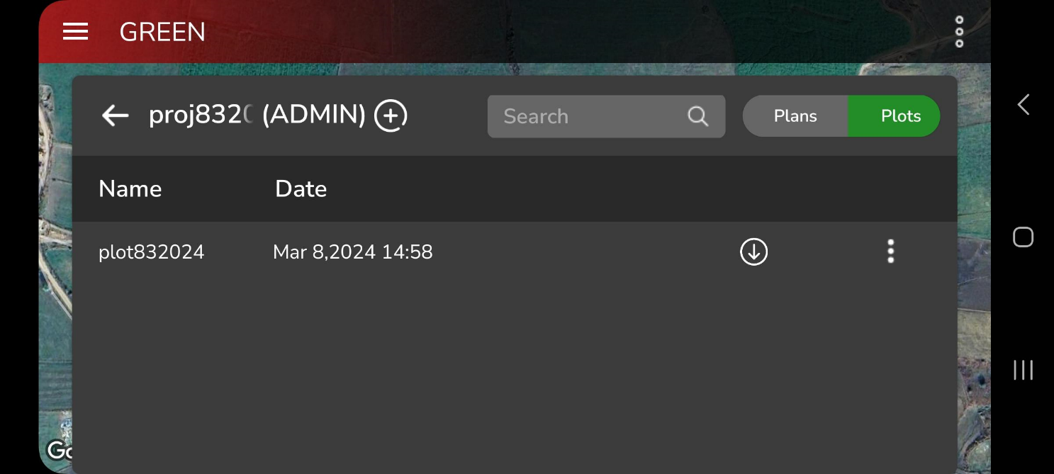
Step 4: Download the Plan or Plot
- Tap the Download
 button next to the selected plan or plot, as shown below.
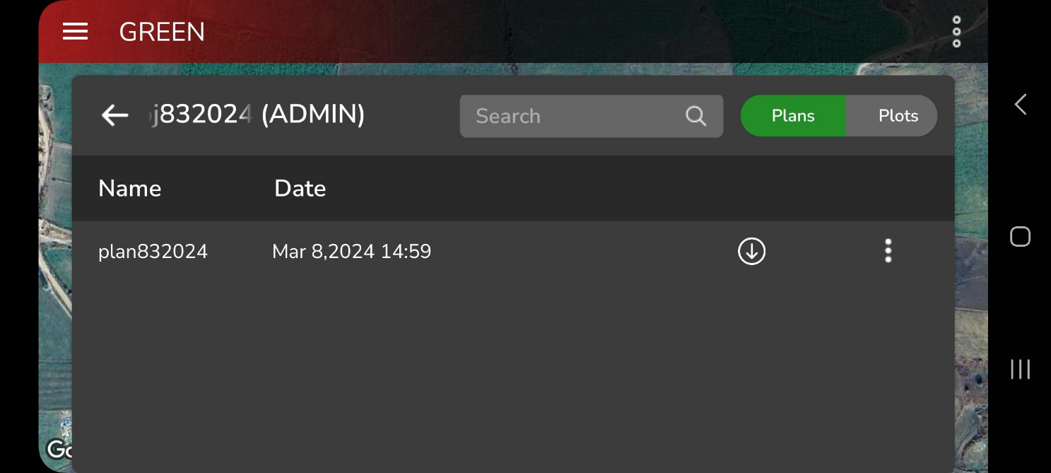

- The selected plan or plot will now be downloaded from AeroGCS Enterprise and saved under your project in AeroGCS GREEN.
Important Notes:
|
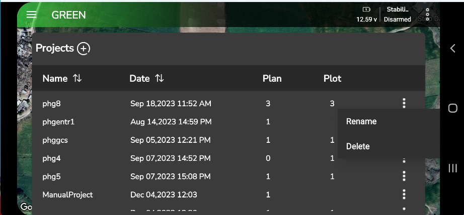
6.3.7. Delete a Project
AeroGCS GREEN lets you delete projects, plans, and plots. When you delete a project, all plans and plots inside that project are removed together and cannot be recovered. You can also delete individual plans or plots from a project, which removes only the selected item.
| Important Note: The ability to delete projects, plans, and plots within AeroGCS GREEN is determined by whether you are logged in to your AeroGCS Enterprise account. |
Scenario 1: Not Logged in to AeroGCS Enterprise
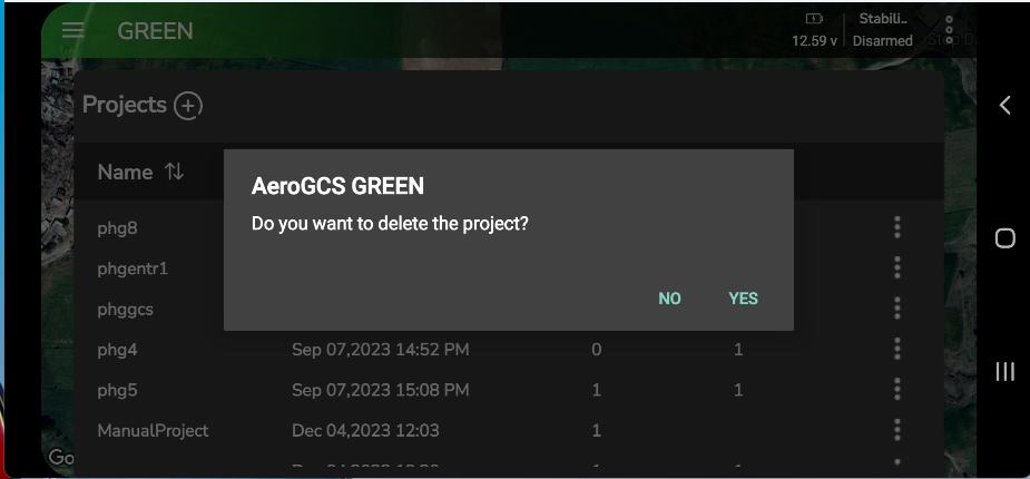
If you are not logged in to AeroGCS Enterprise from within AeroGCS GREEN, you can delete projects, plans, and plots directly in the app. Deleting a project will permanently remove all associated plans and plots.
Steps to delete (not logged in):
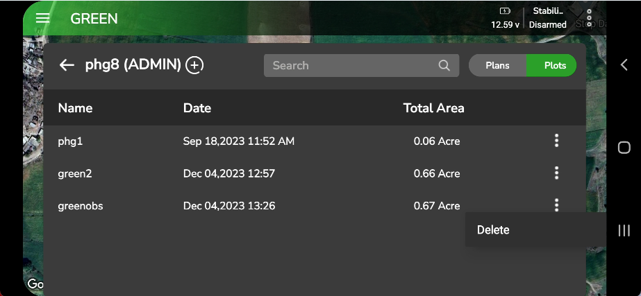
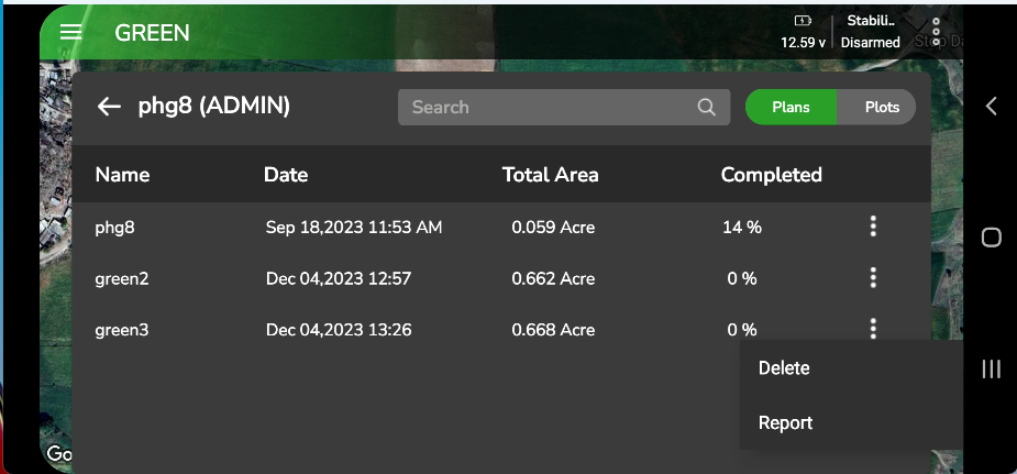
- Delete a plot
- From the plot list, select the plot you want to remove.
- Tap the ⋮ (three dots) at the end of the plot row to open the options.
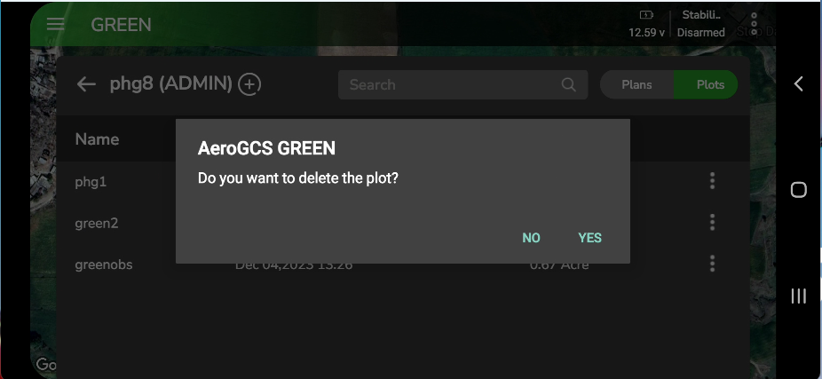
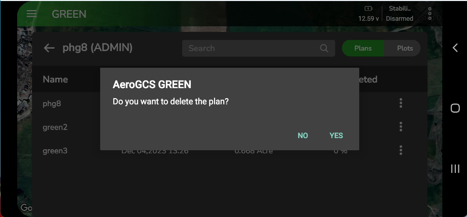
- Tap Delete. A confirmation prompt appears.
- Tap Yes to confirm, or No to cancel.
Scenario 2: Logged in to AeroGCS Enterprise
If you’re logged in to your AeroGCS Enterprise account from within AeroGCS GREEN:
- The rename and delete options for projects are disabled.
- The delete options for plans and plots are disabled.
Reasoning:
Since your projects are now synchronized with AeroGCS Enterprise, any deletions need to be done through the central platform to maintain data consistency.
Solution:
- To delete projects, plans, and plots when logged in, access them directly within AeroGCS Enterprise and delete them using the platform’s tools.
Here’s a summary of the deletion process based on your login status:
Login Status | Project Deletion | Plan Deletion | Plot Deletion |
Not Logged In | Yes (Deletes all associated plans & plots) | Yes | Yes |
Logged in (AeroGCS Enterprise) | Not possible in AeroGCS GREEN | Not possible in AeroGCS GREEN | Not possible in AeroGCS GREEN |