-
AeroGCS CONFIG User Manual
11. Advanced Configuration
The advanced configuration section of AeroGCS CONFIG allows you to configure External Sensors, Tuning, and Spraying Configuration. Follow the steps below for each section to configure them properly.
11.1 External Sensors
This section allows you to configure the obstacle avoidance sensor, altimeter, level sensor, flow meter, and GPS. Additionally, it displays a summary of the configured settings.
To Access External Sensors Settings:
- Click on “Advanced Configuration”.
- Then click on “External Sensors”.
This will display the “External Sensor” screen as shown below.
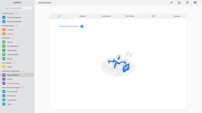
11.1.1 OA (Obstacle Avoidance Sensor)
Add a New External Obstacle Avoidance Sensor
Click the “+” sign to add a new external obstacle avoidance sensor. This will show you the select sensor screen. Select a sensor from the available options in the drop-down list. This will enable parameters to configure external sensors, including R21 Front, R21 Back, and MR72.
1. R21 Front
When you select R21 Front, the screen will appear as shown below.
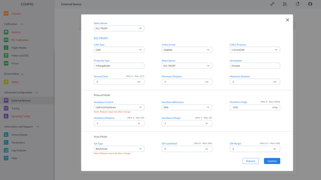
Note: The red highlighting serves as an indicator for both missing parameters and invalid configurations. The default color will be restored once the correct values are entered for these parameters. |
Configure as follows:
R21 Front
- CAN TYPE: Select the value from the drop-down list.
- CAN DRIVER: Select the value from the drop-down list.
- CAN PROTOCOL: Select the value from the drop-down list.
- Proximity Type: Set as range finder.
- Select Sensor: R21 Front.
- Orientation: Forwarded.
- Ground Clearance: Set the value in cm (from 5 to 127).
- Minimum Distance: Set the value in cm.
- Maximum Distance: Set the value in cm.
Manual Mode:
- Avoidance Control: Select the value from the drop-down list.
- Avoidance Behavior: Select the value from the drop-down list.
- Avoidance Angle: Set the value ranging from 0 to 4500 cdeg.
- Avoidance Distance: Set the value from 1 to 30 m.
- Avoidance Margin: Set the value from 1 to 30 m.
Auto Mode:
- OA Type: Select the value from the drop-down list.
- OA Lookahead: Set the value from 0 to 100 m.
- OA Margin: Set the value from 0.1 to 100.
After setting all parameters, click “Update” to send the values to the device. If any parameter is set inaccurately, it will show the corresponding error message.
2. R21 Back
When you select R21 Back, the screen will appear as shown below.

Configure as follows:
R21 Back
- CAN TYPE: Select the value from the drop-down list.
- CAN DRIVER: Select the value from the drop-down list.
- CAN PROTOCOL: Select the value from the drop-down list.
- Proximity Type: Set as range finder.
- Select Sensor: R21 Back.
- Orientation: Forwarded.
- Ground Clearance: Set the value in cm (from 5 to 127).
- Minimum Distance: Set the value in cm.
- Maximum Distance: Set the value in cm.
Manual Mode:
- Avoidance Control: Select the value from the drop-down list.
- Avoidance Behavior: Select the value from the drop-down list.
- Avoidance Angle: Set the value ranging from 0 to 4500 cdeg.
- Avoidance Distance: Set the value from 1 to 30 m.
- Avoidance Margin: Set the value from 1 to 30 m.
Auto Mode:
- OA Type: Select the value from the drop-down list.
- OA Lookahead: Set the value from 0 to 100 m.
- OA Margin: Set the value from 0.1 to 100.
After setting all parameters, click “Update” to send the values to the device. If any parameter is set inaccurately, it will show the corresponding error message.
3. MR72
When you select MR72, the screen will appear as shown below.
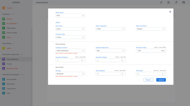
Configure as follows:
MR72
- Select Type: Select the value from the drop-down list.
- Baudrate: Select the value from the drop-down list.
- Protocol: Select the value from the drop-down list.
- Proximity Type: Select the value from the drop-down list.
Manual Mode:
- Avoidance Control: Select the value from the drop-down list.
- Avoidance Behavior: Select the value from the drop-down list.
- Avoidance Angle: Set the value ranging from 0 to 4500 cdeg.
- Avoidance Distance: Set the value from 1 to 30 m.
- Avoidance Margin: Set the value from 1 to 30 m.
Auto Mode:
- OA Type: Select the value from the drop-down list.
- OA Lookahead: Set the value from 0 to 100 m.
- OA Margin: Set the value from 0.1 to 100.
After setting all parameters, click “Update” to send the values to the device. If any parameter is set inaccurately, it will show the corresponding error message.
Note: After adding the external sensor configuration, please don’t forget to reboot the device and reconnect it to AeroGCS CONFIG. |
This completes the process of configuring the external sensor using AeroGCS CONFIG.
11.1.2 Altimeter
To access the Altimeter tab:
- Click on “Altimeter,” which will display the screen as shown below.
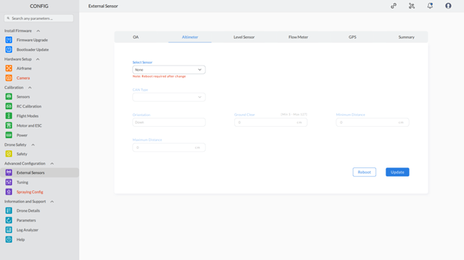

Note: The red highlighting serves as an indicator for both missing parameters and invalid configurations. The default color will be restored once the correct values are entered for these parameters. |
Step 2: Configure the Additional Parameters
- Configure the additional parameters on the screen.
- Click the “Update” button. This will send the parameters to the device with a confirmation message that “parameters are sent.”
Note:
|
11.1.3 Level Sensor
To configure the Level Sensor, follow these steps:
Step 1: Access Level Sensor Configuration
- Navigate to the Advanced Configuration section on the left menu.
- Click on External Sensors to open the configuration screen.
Select the Level Sensor tab at the top of the screen.
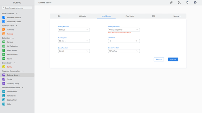
Step 2: Configure Battery Monitor
- Choose the desired battery monitor from the Battery Monitor dropdown menu.
- Example: Select Battery 3 for monitoring the third battery.
Step 3: Configure Auxiliary Pin
- Select the appropriate auxiliary pin from the Auxiliary Pin dropdown menu.
- Example: Choose 50: Aux 1 for the first auxiliary pin.
Step 4: Set Servo Function
- Choose the desired servo function from the Servo Function dropdown menu.
- Example: Select Servo 1 to assign a specific function to Servo 1.
Step 5: Configure Battery3 Monitor
- On the right side of the screen, select the required option from the Battery2 Monitor dropdown menu.
- Example: Choose Synthetic Current and Analog Voltage to set the level sensor.
- Note: Changing this setting may require a reboot, as indicated by the message in red text.
Step 6: Set Low3 Voltage
- Enter the voltage value in the Low3 Volt field.
- Example: Set the voltage to 0 V if no specific low voltage value is required.
Step 7: Set Servo1 Function
- Choose the appropriate servo function from the Servo1 Function dropdown menu.
- Example: Select the RCPassThru function to be assigned to Servo 1.
Step 8: Update Settings
- After configuring all required settings, click the Update button to send the parameters to the device.
Note:
|
By following these steps, you will successfully configure the Level Sensor settings for your drone using the AeroGCS CONFIG software.
11.1.4 Flow meter
To configure the Flow Meter, follow these steps:
Step 1: Access Flow Meter Configuration
- Navigate to the Advanced Configuration section on the left menu.
- Click on External Sensors to open the configuration screen.
- Select the Flow Meter tab at the top of the screen.
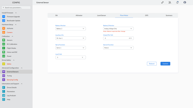
Step 2: Configure Battery Monitor
- Choose the desired battery monitor from the Battery Monitor dropdown menu.
- Example: Select Battery 2 for monitoring the second battery.
Step 3: Configure Auxiliary Pin
- Select the appropriate auxiliary pin from the Auxiliary Pin dropdown menu.
- Example: Choose 50: Aux 1 for the first auxiliary pin.
Step 4: Set Servo Function
- Choose the desired servo function from the Servo Function dropdown menu.
- Example: Select Servo 1 to assign a specific function to Servo 1.
Step 5: Configure Battery2 Monitor
- On the right side of the screen, select the required option from the Battery2 Monitor dropdown menu.
- Example: Select FuelFlow to monitor fuel flow.
- Note: Changing this setting may require a reboot, as indicated by the message in red text.
Step 6: Set Amps2 per Volt
- Enter the value of Amps2 per Volt in the Amps2 per Volt field.
- Example: Set the value to 0 if no specific Amps2 per Volt value is required.
Step 7: Set Servo1 Function
- Choose the appropriate servo function from the Servo1 Function dropdown menu.
- Example: Select Disabled if no function is to be assigned to Servo 1.
Step 8: Set Low2 per Volt
- Enter the value of Low2 per Volt in the Low2 per Volt field.
- Example: Set the value to 0 if no specific Low2 per Volt value is required.
Step 9: Update Settings
- After configuring all required settings, click the Update button to send the parameters to the device.
Note: 1. Don’t forget to reboot the device by clicking the “Reboot” button. |
By following these steps, you will successfully configure the Flow Meter settings for your drone using the AeroGCS CONFIG software.
11.1.5 GPS
Configuring GPS Sensor
To configure the GPS Sensor, follow these steps:
Step 1: Access GPS Sensor Configuration
- Navigate to the Advanced Configuration section on the left menu.
- Click on External Sensors to open the configuration screen.
Select the GPS tab at the top of the screen.
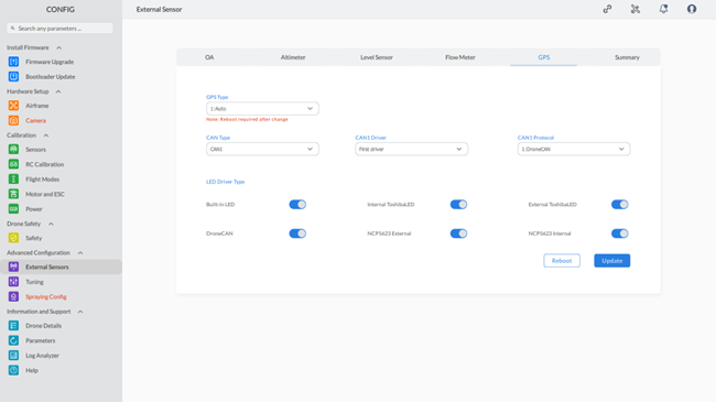
GPS Sensor Configuration
Step 2: Select GPS Type
- Choose the desired GPS type from the GPS Type dropdown menu.
- Example: Select GPS Type 2 for a specific GPS type.
Step 3: Select CAN Type
- Choose the appropriate CAN type from the CAN Type dropdown menu.
- Example: Choose CAN Type 1 for a specific CAN type.
Step 4: Select CAN Driver
- Choose the desired CAN driver from the CAN Driver dropdown menu.
- Example: Select CAN Driver A for a specific CAN driver.
Step 5: Select CAN Protocol
- Choose the desired CAN protocol from the CAN Protocol dropdown menu.
- Example: Select CAN Protocol 3 for a specific CAN protocol.
Step 6: Toggle LED Driver Type
- Enable or disable the LED driver type using the toggle buttons.
- Example: Toggle ON to enable LED driver type, or OFF to disable it.
Step 7: Update Settings
- After configuring all required settings, click the Update button to send the parameters to the device.
Note:
|
By following these steps, you will successfully configure the GPS Sensor settings for your drone using the AeroGCS CONFIG software.
11.1.6 Summary
Viewing Summary of Configured External Sensors
To see a summary of the configured external sensors, follow these steps:
Step 1: Access External Sensors Summary
- Navigate to the Advanced Configuration section on the left menu.
- Click on External Sensors to open the configuration screen.
- Select the Summary tab at the top of the screen.
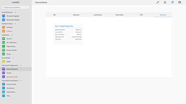
External Sensors Summary
Here, you can view a summary of all configured external sensors, including GPS, level sensors, and any other connected peripherals. This summary provides an overview of the current configuration settings for your drone’s external sensors, allowing you to easily review and verify your setup.
11.2 Tuning
In AeroGCS CONFIG, you can enhance your drone’s stability using Basic tuning, Advanced tuning, and the Auto Tuning facility.
To Access Tunning Settings:
- Click on “Advanced Configuration”.
- Then click on “Tunning”.
This will display the “Tunning” screen as shown below.
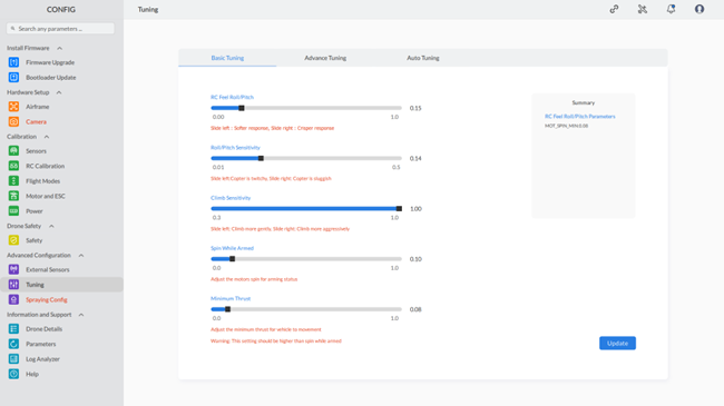
11.2.1 Basic Tunning
To configure the Basic tuning settings, follow these steps:
Step 1: Access Tuning Configuration
- Navigate to the Advanced Configuration section on the left menu.
- Click on Tuning to open the tuning configuration screen.
- Select the Basic Tuning tab at the top of the screen.
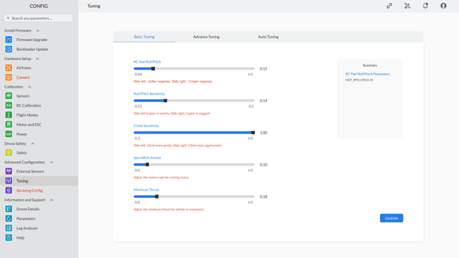
Step 2: Adjust RC Feel Roll/Pitch
- Use the slider for RC Feel Roll/Pitch to set the desired value.
- Example: Set the value to 0.15.
- Note: Sliding left provides a softer response while sliding right provides a crisper response.
Step 3: Adjust Roll/Pitch Sensitivity
- Use the slider for Roll/Pitch Sensitivity to set the desired value.
- Example: Set the value to 0.14.
- Note: Sliding left makes the copter twitchy while sliding right makes it sluggish.
Step 4: Adjust Climb Sensitivity
- Use the slider for Climb Sensitivity to set the desired value.
- Example: Set the value to 1.00.
- Note: Sliding left allows the copter to climb more gently while sliding right makes it climb more aggressively.
Step 5: Adjust Spin While Armed
- Use the slider for Spin While Armed to set the desired value.
- Example: Set the value to 0.10.
- Note: This adjusts the motors’ spin for arming status.
Step 6: Adjust Minimum Thrust
- Use the slider for Minimum Thrust to set the desired value.
- Example: Set the value to 0.07.
- Note: Adjusts the minimum thrust for vehicle movement. This setting should be higher than the spin while armed value.
Step 7: Update Settings
- After configuring all required settings, click the Update button to save the changes.
By following these steps, you will successfully configure the basic tuning settings for your drone using the AeroGCS CONFIG software.
11.2.2 Advanced Tuning
To configure the advanced tuning settings, follow these steps:
Step 1: Access Advanced Tuning Configuration
- Navigate to the Advanced Configuration section on the left menu.
- Click on Tuning to open the tuning configuration screen.
- Select the Advance Tuning tab at the top of the screen.
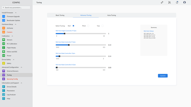
Step 2: Select Tuning Axis
- Choose the axis you want to tune by selecting one of the options at the top:
- Roll
- Pitch
- Yaw
Step 3: Adjust Roll Axis Angle Controller P Gain
- Use the slider for Roll Axis Angle Controller P Gain to set the desired value.
- Example: Set the value to 5.
- Note: This controls the proportional gain for the roll angle.
Step 4: Adjust Roll Axis Rate Controller P Gain
- Use the slider for Roll Axis Rate Controller P Gain to set the desired value.
- Example: Set the value to 0.14.
- Note: This controls the proportional gain for the roll rate.
Step 5: Adjust Roll Axis Rate Controller I Gain
- Use the slider for Roll Axis Rate Controller I Gain to set the desired value.
- Example: Set the value to 0.14.
- Note: This controls the integral gain for the roll rate.
Step 6: Adjust Roll Axis Rate Controller D Gain
- Use the slider for Roll Axis Rate Controller D Gain to set the desired value.
- Example: Set the value to 0.00.
- Note: This controls the derivative gain for the roll rate.
Step 7: Update Settings
- After configuring all required settings, click the Update button to save the changes.
Summary
The summary section on the right will display the updated values for the selected tuning axis.
By following these steps, you will successfully configure the advanced tuning settings for your drone using the AeroGCS CONFIG software.
11.2.3 Auto Tuning
To configure the auto-tuning settings, follow these steps:
Step 1: Access Auto Tuning Configuration
- Navigate to the Advanced Configuration section on the left menu.
- Click on Tuning to open the tuning configuration screen.
- Select the Auto Tuning tab at the top of the screen.
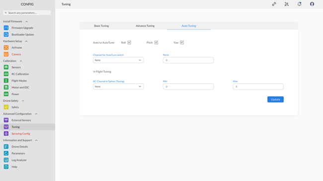
Step 2: Select Axes for AutoTune
- Choose the axes you want to auto-tune by selecting the checkboxes:
- Roll
- Pitch
- Yaw
Step 3: Configure AutoTune Settings
- Channel for AutoTune switch:
- Select the channel used for the AutoTune switch from the dropdown menu.
- Example: Channel 7.
- RC7 Option:
- Enter the RC option number for the selected channel.
- Example: 17.
- In Flight Tuning:
- RC Channel 6 Option (Tuning):
- Select the tuning parameter for RC Channel 6.
- Example: Stab Roll/Pitch kP.
- Min: Enter the minimum value for the tuning parameter.
- Example: 0.
- Max: Enter the maximum value for the tuning parameter.
- Example: 0.
- RC Channel 6 Option (Tuning):
Step 4: Update Settings
- After configuring all required settings, click the Update button to save the changes.
Summary
The summary section will display the updated auto-tuning settings for the selected axes and channels.
By following these steps, you will successfully configure the auto-tuning settings for your drone using the AeroGCS CONFIG software. This will enable your drone to optimize its flight parameters for improved performance.
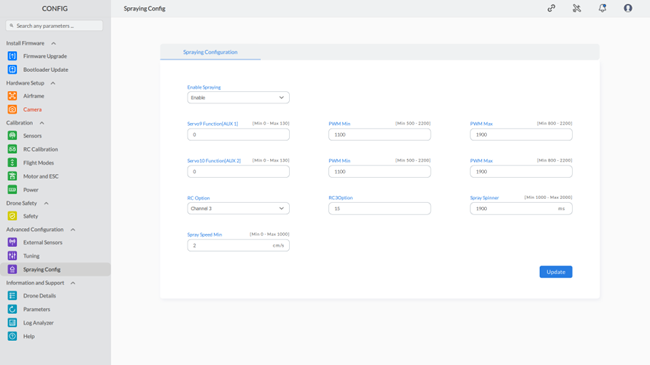
11.3 Spraying Config
To configure the spraying settings, follow these steps:
Step 1: Access Spraying Configuration
- Navigate to the Advanced Configuration section on the left menu.
- Click on Spraying Config to open the spraying configuration screen.
Note: The red highlighting serves as an indicator for both missing parameters and invalid configurations. The default color will be restored once the correct values are entered for these parameters. |
Step 2: Enable Spraying
- Set the Enable Spraying option to Enable from the dropdown menu.
Step 3: Configure Servo Functions
- Servo9 Function (AUX 1):
- Enter the function value for Servo9.
- Example: 22 (Min 0 – Max 130).
- Servo10 Function (AUX 2):
- Enter the function value for Servo10.
- Example: 0 (Min 0 – Max 130).
Step 4: Set PWM Values
- PWM Min:
- Enter the minimum PWM value.
- Example: 1100 (Min 500 – Max 2200).
- PWM Max:
- Enter the maximum PWM value.
- Example: 1900 (Min 800 – Max 2200).
Step 5: Assign RC Option
- RC Option:
- Select the RC option from the dropdown menu.
- Example: Channel 3.
Step 6: Configure Additional Settings
- Spray Speed Min:
- Enter the minimum spray speed.
- Example: 1900 cm/s (Min 0 – Max 1000).
- Spray Spinner:
- Enter the spray spinner value.
- Example: 1900 ms (Min 1000 – Max 2000).
Step 7: Update Settings
- After configuring all required settings, click the Update button to save the changes.
By following these steps, you will successfully configure the spraying settings for your drone using the AeroGCS CONFIG software. This ensures your drone is properly set up for spraying operations, optimizing its performance and efficiency.