-
AeroGCS CONFIG User Manual
9. Calibration
AeroGCS CONFIG provides calibration and settings facilities for sensors, RC calibration, flight modes, motor and ESC, and power in the “Calibration” section.
9.1 Sensors
To do “Sensors” calibration from the “Calibration” section of “CONFIG,” follow these steps:
Step 1: Navigate to “Calibration” under “CONFIG.”
Step 2: Click on “Sensors.”
This will allow you to calibrate various sensors, including the accelerometer, compass, level horizon, pressure, and flow meter. The screen will appear as shown below:
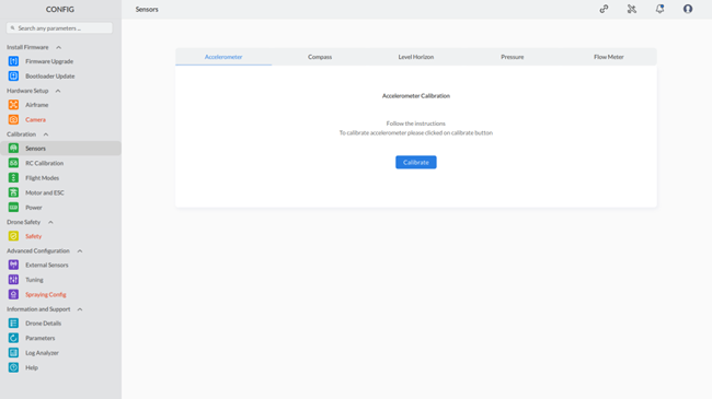
Note: Upon drone connection, the screen displays whether the current sensor is calibrated or not. |
Here are the steps to calibrate each sensor:
9.1.1 Accelerometer Calibration:
To calibrate the accelerometer, follow these steps:
Step 1: Access the Accelerometer Calibration
- Click on the “Accelerometer” tab on the screen to open the calibration section.
- Click on the “Calibrate” button to initiate the calibration process for the accelerometer.
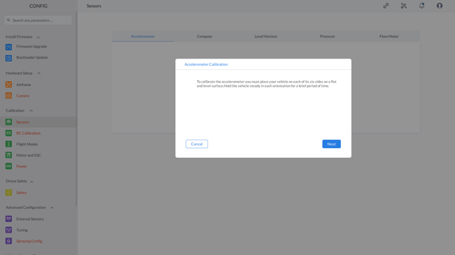
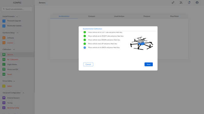
3. A dialog box will appear displaying information about the calibration process, along with “Next” and “Cancel” buttons. Read the information carefully.
Step 2: Start the Calibration
- Click on the “Next” button to begin the calibration.
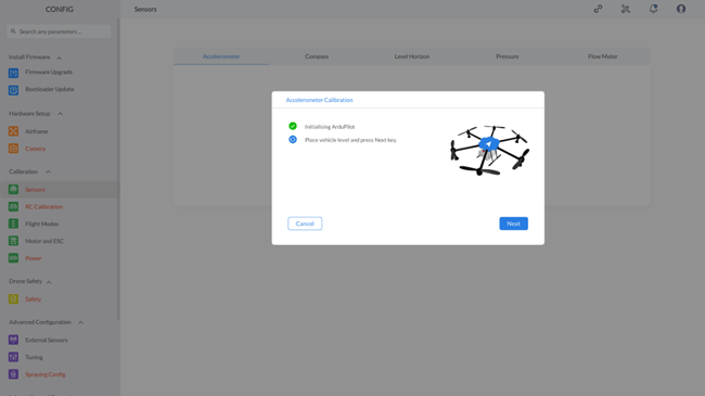
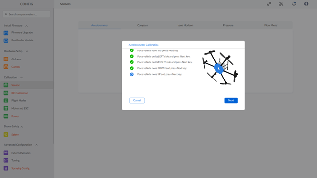
- Follow the on-screen instructions to complete the accelerometer calibration. The process will be illustrated with the following sequence of screens:
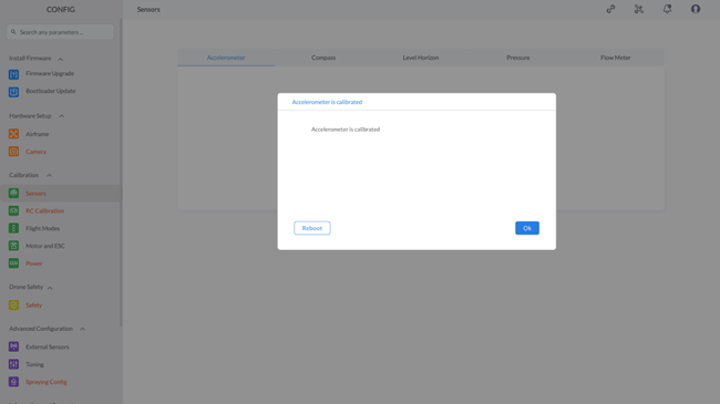
Step 3: Reboot the Device
- Click on the “Reboot” button to restart the device.
- A dialog box will appear with the message “Communication link not established. Please wait” and an “Ok” button.
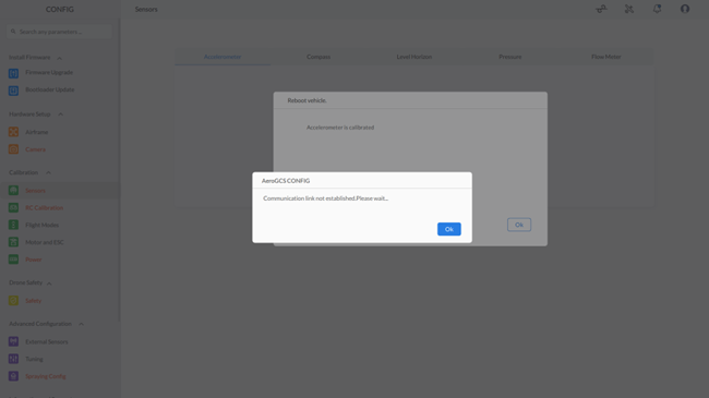
3. Click on “OK”. This will bring up the “Connect to device” screen.
Step 4: Reconnect the Device
- Reconnect the device with AeroGCS CONFIG.
- This completes the accelerometer calibration process.
By following these steps, you will successfully calibrate the accelerometer on your device.
9.1.2 Compass Calibration
To calibrate the Compass, follow these steps:
Step 1: Access Compass Calibration
Click on the “Compass” tab on the screen to open the calibration section. As shown
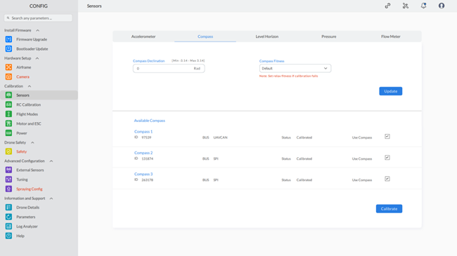
Note: The red highlighting serves as an indicator for both missing parameters and invalid configurations. The default color will be restored once the correct values are entered for these parameters. |
This screen allows you to set values for “Compass Declination” and “Compass Fitness.” It also displays the available compasses for calibration.
Step 2: Set Compass Declination and Fitness
- Set the value for “Compass Declination” from the range -3.14 to 3.14.
- Select “Compass Fitness” from the drop-down list.
- Click on the “Update” button to send the parameters to the vehicle.
- A message will appear stating “Parameters are sent to the device.”
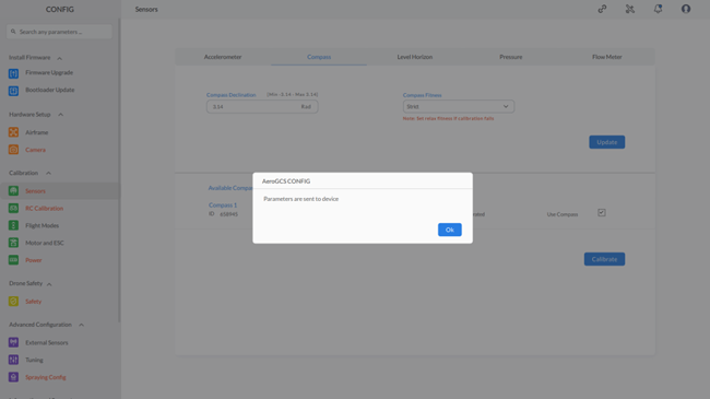
5. Click the “OK” button to return to the Compass Calibration screen. On this screen, you will see the available compasses for calibration under the label “Available Compass.
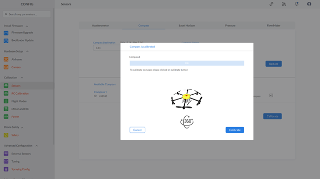
Step 3: Start Compass Calibration
- Select the compass to calibrate by checking the checkbox in front of the compass.
- Click the “Calibrate” button to start the compass calibration.
4. Once the process is 100% complete, the completion screen will appear.
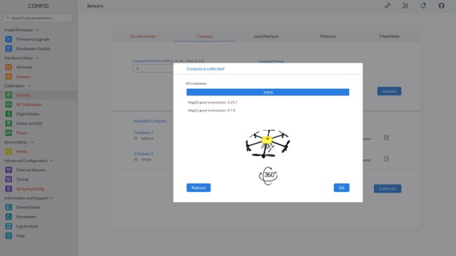
Step 4: Reboot the Device
- Click the “Reboot” button to restart the device.
- The “Connect to Device” screen will appear after rebooting.
- Click the “Connect” button to reconnect the device.
This completes the compass calibration process.
9.1.3 Level Horizon Calibration
To calibrate the Level Horizon, follow these steps:
Step 1: Access Level Horizon Calibration
- Click on the “Level Horizon” tab on the screen to open the calibration section.
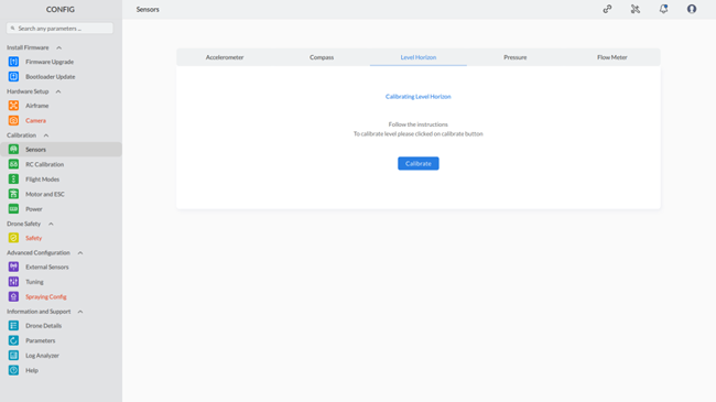
Step 2: Start Level Horizon Calibration
1.Click the “Calibrate” button to initiate the Level Horizon calibration process.
2. Follow the on-screen instructions to ensure your device is on a level surface. The system will automatically adjust and level the horizon.
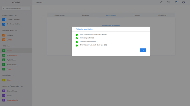
Step 3: Confirm Calibration
– Click the “OK” button to complete the Level Horizon calibration process.
This completes the Level Horizon calibration process.
9.1.4 Pressure Sensor Calibration
To calibrate the Pressure Sensor, follow these steps:
Step 1: Access Pressure Sensor Calibration
Click on the “Pressure” tab on the screen to open the calibration section.

Step 2: Start Pressure Sensor Calibration
- Ensure the drone is in a stable environment with no air movement.
- Click the “Calibrate” button to initiate the Pressure Sensor calibration process.
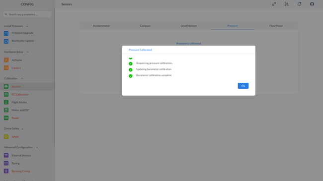
Step 3: Confirm Calibration
- Click the “OK” button to complete the Pressure Sensor calibration process.
This completes the Pressure Sensor calibration process.
9.1.5 Flow Meter Calibration
To calibrate the Flow Meter, follow these steps:
Step 1: Access Flow Meter Calibration
- Click on the “Flow Meter” tab on the screen to open the calibration section.
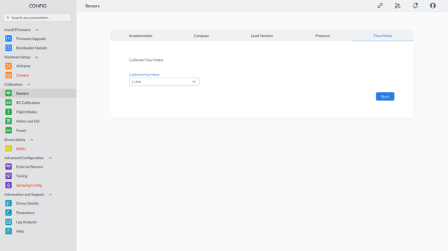
Step 2: Select Liquid to Calibrate Flow Meter
- Choose the quantity of liquid (in liters) used for flow meter calibration from the dropdown list “Calibrate Flow Meter”.
- Follow any specific instructions provided for your drone model.
- Click the “Start” button to begin the Flow Meter calibration process.
Step 3: Follow Instructions
- Follow the on-screen instructions such as “Please stop as soon as the tank becomes empty” to complete the calibration process.
- Click the “Stop” button when instructed.
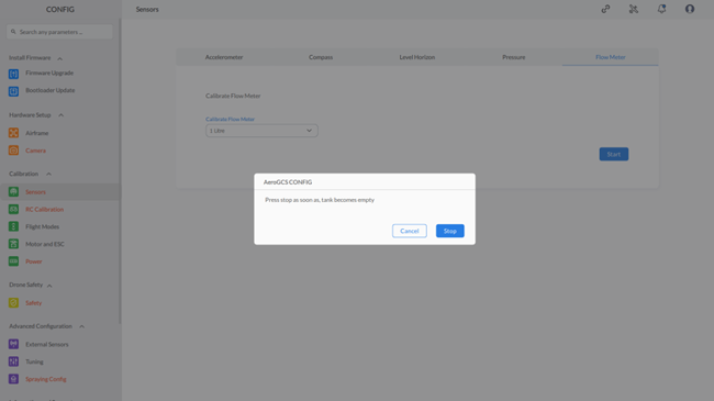
Step 4: Confirm Calibration
- Click the “OK” button to finalize the Flow Meter calibration process.
This completes the Flow Meter calibration process.
9.2 RC Calibration
To do “RC” calibration from the “Calibration” section of “CONFIG,” follow these steps:
Step 1: Navigate to “Calibration” under “CONFIG.”
Step 2: Click on “RC Calibration.”
This will allow you to calibrate various settings, including RC Calibration, Attitude Channel, Attitude Monitor, and RC Safety Switch. The screen will appear as shown below:
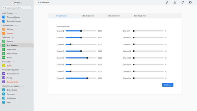
9.2.1 RC Calibration:
Step 1: Click on “RC Calibration”
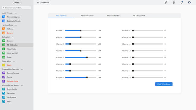
Step 2: Click on the “Calibrate” button on the screen. Read and follow the on-screen instructions. After completing the calibration process, the following screen will be displayed:
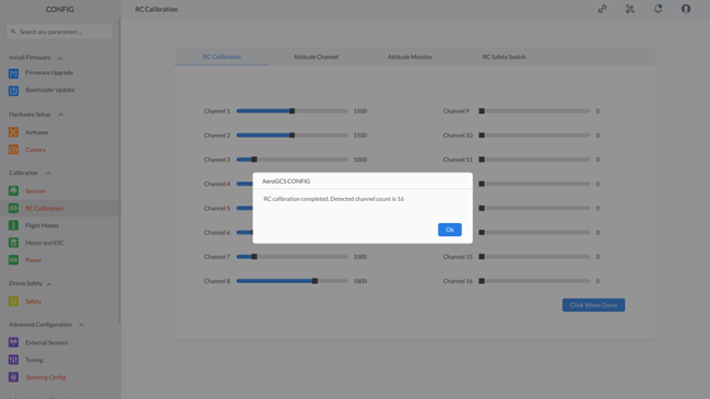
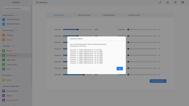
After clicking “OK,” the screen will display the detected RC values with their corresponding minimum and maximum values, as shown below :
9.2.2 Attitude Channel
To configure altitude channel settings, navigate to the Attitude Chanel section of the screen in RC Calibration, as shown below:
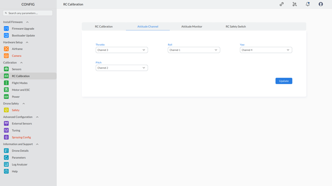
Step 1: Select Channels: From the dropdown list, choose the suitable channels for Throttle, Roll, Yaw, Pitch
Step 2: Update Settings: Click the “Update” button to transmit the configured values to the drone. This will show the “Parameters are sent to device” message.
Step 3: Complete the process by clicking the “OK” button.
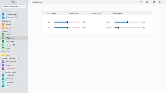
9.2.3 Attitude Monitor
Navigate to the “Attitude Monitor” section on the “RC Calibration” screen.
The Attitude Monitor section of the RC Calibration shows the values of roll, pitch, yaw, and throttle set for the drone, as shown below:
9.2.4 RC Safety Switch
Step 1: Go to the “RC Calibration” screen and navigate to the “RC Safety Switch” section. The screen will appear as shown below:
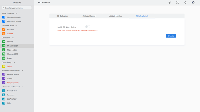
Step 2: Enable or Disable the RC Safety Switch
- To enable the RC Safety Switch, click on the toggle button.
- To disable the RC Safety Switch, use the same toggle button.
This will configure the RC Safety Switch.
Step 3: Click “Update” to apply the changes. A confirmation message, “Parameters are sent to the device,” indicates successful updating.
Step 4: Click “OK” to complete the process.
9.3 Flight Modes
Navigate to the “Flight Modes” section under “Calibration” in the “CONFIG” menu. The Flight Modes screen will be shown
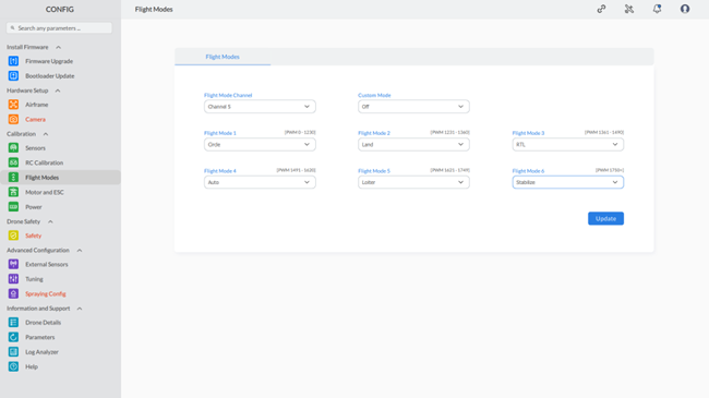
Step 1: To select the appropriate values for Flight Mode Channel, Custom Mode, and Flight Mode from 1 to 6, follow these steps:
- Flight Mode Channel:
- Click on the drop-down menu next to “Flight Mode Channel.”
- Choose the desired value from the available options.
- Custom Mode:
- Click on the drop-down menu next to “Custom Mode.”
- Select the preferred option from the list provided.
- Flight Mode (For each Flight Mode, repeat the following step):
- Click on the drop-down menu next to “Flight Mode.”
- Choose the appropriate mode from the options.
Ensure that you select the values that align with your specific requirements and operational preferences.
Step 2: Click “Update” to apply the changes. A confirmation message, “Parameters are sent to the device,” indicates successful updating.
Step 3: Click “OK” to complete the process.
9.4 Motor and ESC
The Motor and ESC Configuration screen allows you to test and calibrate your drone’s motors and Electronic Speed Controllers (ESCs). This section will guide you through the steps necessary to ensure your motors are functioning correctly and spinning in the correct directions.
Navigate to the “Motor and ESC” section under “Calibration” in the “CONFIG” menu. The Motor and ESC screen will be shown
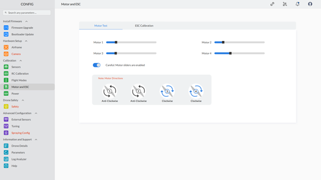
9.4.1 Motor Test
To conduct a comprehensive test of the motors using the provided toggle button and sliders, adhere to the following steps:
Activation of Motor Test Mode
1. Enable Motors:
- Utilize the toggle button on the interface to activate the motor sliders for testing.
Adjustment of Motor Sliders
2. Fine-tune Motor Speed:
- Locate and manipulate the four motor sliders designated as Motor 1, Motor 2, Motor 3, and Motor 4.
- Precisely adjust each slider to regulate the speed of the corresponding motor.
- Monitor the response of each motor to ensure accurate adjustments.
Confirmation of Motor Rotation
3. Validate Motor Directionality:
- Refer to the graphical representation positioned beneath the sliders to confirm the intended rotational direction for each motor:
Motor 1: Anticipated rotation is Anti-Clockwise
Motor 2: Intended rotation is Anti-Clockwise
Motor 3: Expected rotation is Clockwise
Motor 4: Desired rotation is Clockwise - Visually confirm that the motion of each motor aligns with the specified direction.
4. Addressing Incorrect Rotation:
– In the event of any motor rotating in an unintended direction:
– Adjust Motor Wiring: Swap any two out of the three wires connected to the motor to reverse its rotation.
– Modify ESC Configuration: Alternatively, revise the motor direction setting within the ESC configuration.
By meticulously adhering to these instructions, you can effectively assess and rectify any deviations in the functionality and rotational alignment of each motor on your drone.
9.4.2 ESC Calibration
Navigate to the “ESC Calibration” section under “Calibration” in the “CONFIG” menu. The Motor and ESC screen will be shown
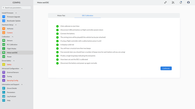
Step 1: Read and Follow On-Screen Instructions:
- Begin by carefully reading and adhering to the instructions displayed on the screen.
Step 2: Click on the “Calibrate” Button:
- Once you have read the instructions, locate and click on the “Calibrate” button as directed.
Step 3: Follow On-Screen Calibration Steps:
- After clicking the “Calibrate” button, meticulously execute each step outlined on the screen to complete the calibration process.
Step 4: Confirmation of Calibration Completion:
- After following the on-screen calibration steps, verify that the process has been completed.
9.5 Power
Navigate to the “Power” section under “Calibration” in the “CONFIG” menu. The Motor and ESC screen will be shown

Note: The red highlighting serves as an indicator for both missing parameters and invalid configurations. The default color will be restored once the correct values are entered for these parameters. |
Step 1: Configure Power Settings
Configure the power settings by selecting and setting values for each parameter:
- Battery Monitor: Choose between monitoring analog voltage and current or just analog voltage.
- Battery Capacity: Set your battery’s maximum capacity in mAh (milliampere hours).
- Minimum Arming Voltage: Set the minimum voltage triggering a low battery alarm to prevent mid-flight power depletion.
- Power Sensor: Select the power sensor for measuring battery voltage and current.
- Current Pin & Voltage Pin: Designate flight controller pins for battery current and voltage sensors or disable if not applicable.
- Voltage Multiplier & Amps per Volt: Calibrate battery voltage and current readings:
-Measure the battery voltage with a voltmeter and enter the value into the “Measured Voltage” field.
– Click “Calculate” to determine the voltage multiplier and Amps per volt value.
- Amps Offset: Enter any offset value for current readings in Amps, if necessary.
Step 2: Click “Update” to apply the changes. A confirmation message, “Parameters are sent to the device,” indicates successful updating.
Step 3: Click “OK” to complete the process.