-
AeroGCS DEFENCE
3. Flight View and Dashboard
After successful installation and login, the AeroGCS DEFENCE application opens directly into the Flight View interface. This operational interface functions as the central dashboard for managing drone operations, visualizing live positioning, accessing telemetry, and executing missions. It is the primary workspace from which all mission-critical interactions are performed.
Designed to support fully offline operations, AeroGCS DEFENCE ensures data privacy, security, and continuous availability, making it ideal for field deployments in defence and surveillance scenarios.
This chapter introduces the key visual and functional elements of the Flight View, including:
- Map display and mission overlays
- Real-time drone telemetry and orientation indicators
- Drone head directional cues (target, current, and active point)
- Central control toolbar and mission utilities
- Quick-access menus and system configuration options
Each section in this chapter explains a specific part of the interface layout to help users quickly understand how to navigate and operate within the Flight View.
3.1 Navigating the Flight View
Flight View
| Region | Description |
| Top Global Controls | Displays system-level indicators including battery voltage, GPS lock, connection status, notifications, and flight mode. |
| Left Toolbar | Quick-access controls for Takeoff, Land, RTL, Pause, Resume, Arm, and Disarm. |
| Map View (Central Area) | Main map view with real-time drone position, heading paths, and waypoints. |
| Top-Right Control Cluster | Direct tools for: Center Position, Map Layer Toggle, Camera Toggle. |
| Top-Right Three-Dot Menu | Opens settings, logs, map tools, and user management options. |
| Bottom Telemetry Panel | Live display of altitude, time, distance, RSSI, speed, and battery metrics. |
| Directional Compass | Shows drone orientation and heading. |
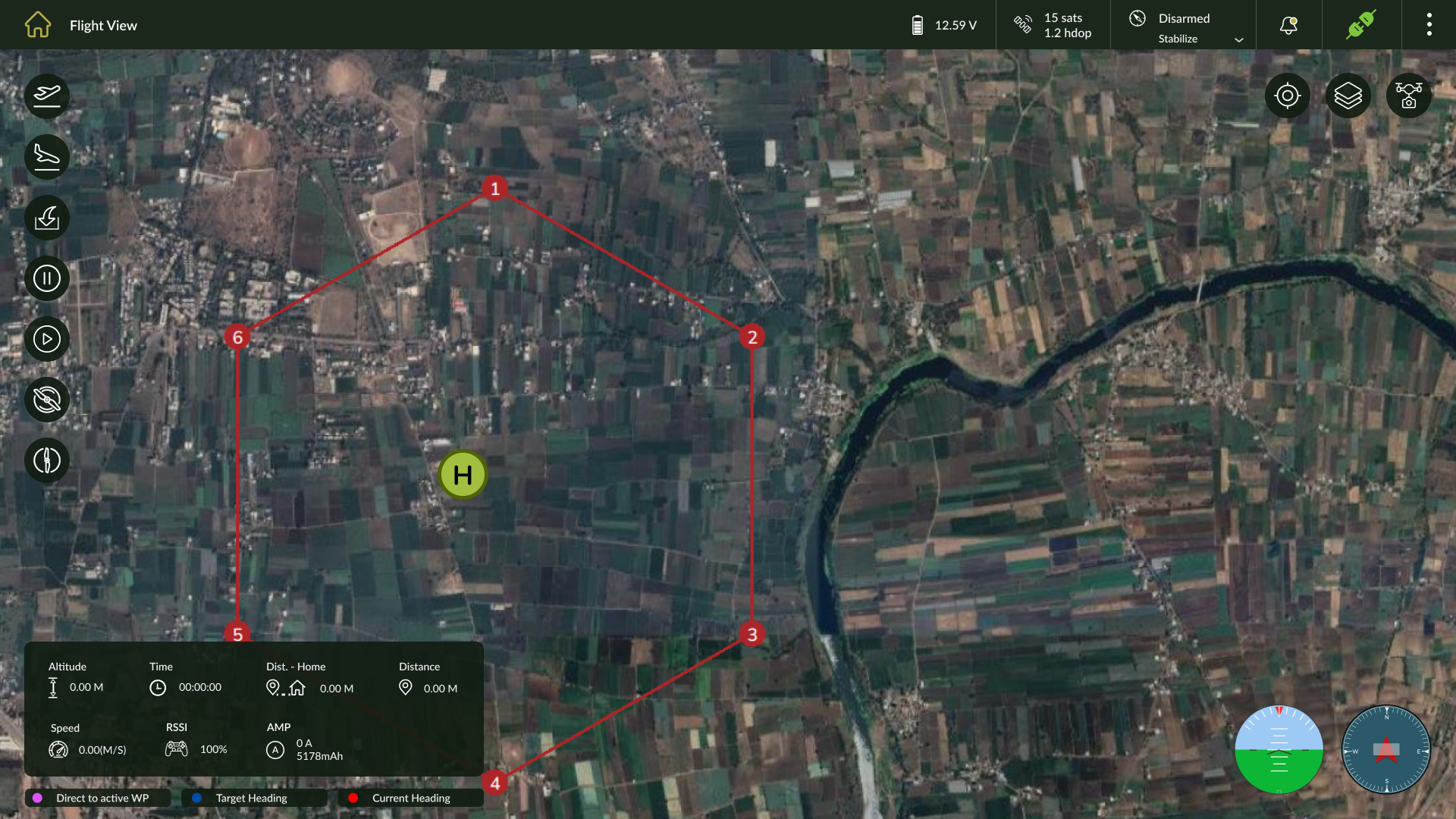
Heading Indicators
| Indicator | Color | Function |
| Direct to Active WP | Pink | Path toward the currently selected waypoint. |
| Target Heading | Blue | Intended directional heading. |
| Current Heading | Red | Drone’s real-time orientation. |
Flight Control Panel
| Control | Function |
| Takeoff | Initiates automatic takeoff sequence. |
| Land | Commands landing at the current location. |
| RTL | Executes Return-to-Launch (RTL) maneuver. |
| Pause | Temporarily halts the mission. |
| Resume | Resumes the paused mission. |
| Arm | Arms motors for flight. |
| Disarm | Disarms motors for safety. |
| Object Drop | To Drop Object manually during fly. |
Central Map View
| Feature | Description |
| Waypoints | Displayed as numbered points representing the mission plan. |
| Drone Icon | Real-time position of drone on the map. |
| Heading Paths | Colored lines for drone direction (blue = target, red = current, pink = active WP). |
| Vector/Raster Overlay | Displays imported .shp/.geojson or .tif files for mission planning. |
Top-Right Control Cluster
| Control | Function |
| Center Position Control | Re-centers the drone location on the map view. |
| Map Layer Selection | Switches between different map layers (e.g., Satellite, Terrain, Vector). |
| Camera Toggle | Enables or disables the on-screen camera view overlay. |
Top Global Controls
| Element | Function |
| Battery Voltage | Displays current onboard battery voltage. |
| GPS Status | Number of satellites and HDOP value. |
| Flight Mode | Current flight mode (e.g., Stabilize, Auto, RTL). |
| Notifications | Shows system alerts or status messages. |
| Connection Indicator | Displays connected/disconnected status of telemetry link. |
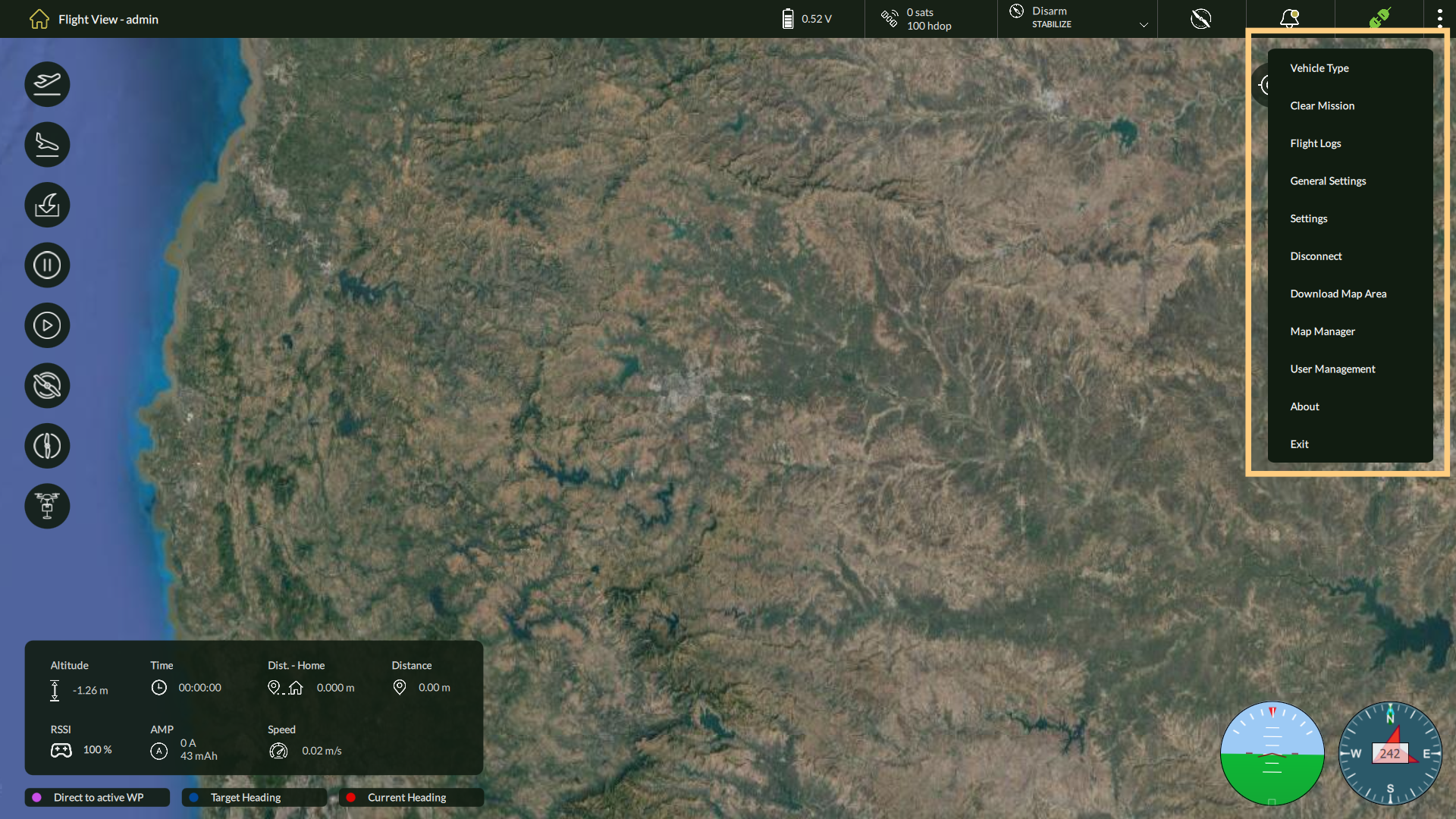
Menu Options
| Menu Option | Function |
| Vehicle Type | Select the drone model/type. |
| Clear Mission | Remove all waypoints and mission data. |
| Flight Logs | View logs of completed missions. |
| General Settings | Access general application preferences. |
| Settings | Configure specific operational parameters. |
| Connect | Establish communication with the drone hardware. |
| Download Map Area | Download satellite maps for offline use. |
| Map Manager | Manage available map sources and tiles. |
| User Management | Add, edit, or delete user accounts. |
| About | View application version and developer info. |
| Exit | Exit the application safely. |
Operational Notes
- Flight View operates fully offline; users must download map areas in advance.
- Real-time telemetry is updated via connected ground control hardware.
- All critical tools are available on-screen with minimal navigation needed.
- Designed for efficiency and accuracy in field operations.
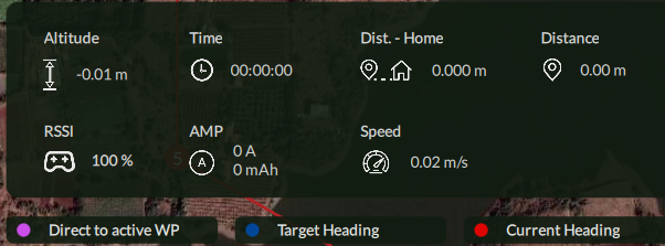
3.2. Telemetry and Status Panel
Key Parameters Displayed
| Field | Description |
| Altitude | Displays the current altitude of the drone relative to its takeoff point. |
| Time | Shows the elapsed flight time since takeoff. |
| Distance from Home | Indicates how far the drone is from its home position (takeoff location). |
| Distance | Represents the total distance travelled by the drone during the mission. |
| RSSI | Reflects the Received Signal Strength Indicator—used to assess signal quality. |
| AMP | Displays current power consumption in amperes, helping monitor energy draw. |
| Speed | Shows the drone’s current speed, updated in real time. |
Operational Relevance
This panel serves as a mission-critical diagnostic tool, allowing the operator to:
- Monitor drone positioning and return distance
- Observe battery draw and signal health
- Evaluate overall flight efficiency and safety in real-time
3.3. Notifications and Alerts
AeroGCS DEFENCE provides real-time visual alerts and notifications to keep operators informed about system events, warnings, and mission-critical conditions. These alerts are accessible via the notification icon located in the top global status bar on the Flight View screen.
This non-intrusive notification mechanism ensures that important information is relayed without interrupting mission flow, which is essential during live surveillance or defence operations.
Notification Center Access
| UI Element | Description |
| Notification Icon | Located in the top-right status bar, this icon indicates the presence of alerts or system messages. |
| Alert Counter | Displays a badge with the number of new/unread notifications. |
| Click Action | Clicking the icon opens a list of recent system messages, warnings, or operational alerts. |
Types of Notifications
| Type | Description |
| System Alerts | Software-level notifications (e.g., activation issues, hardware status). |
| Telemetry Warnings | Alerts related to RSSI loss, low battery, GPS lock issues. |
| Mission Events | Messages related to mission status: takeoff complete, plan paused, etc. |
| Connection Status | Drone connected/disconnected alerts shown in both top bar and log. |
Importance of Real-Time Alerts
- Promotes proactive decision-making in dynamic mission environments
- Minimizes risks due to low signal, unexpected disconnection, or power drop
- Ensures auditability by logging each alert event in flight logs
3.4 Map Layer Selection
Accessing Map Layer Options
To switch between different map layers:
- Navigate to the Flight View
- Click the Map Layer button located in the top-right corner of the interface. The Map Layer icon appears as a stack of three layers.
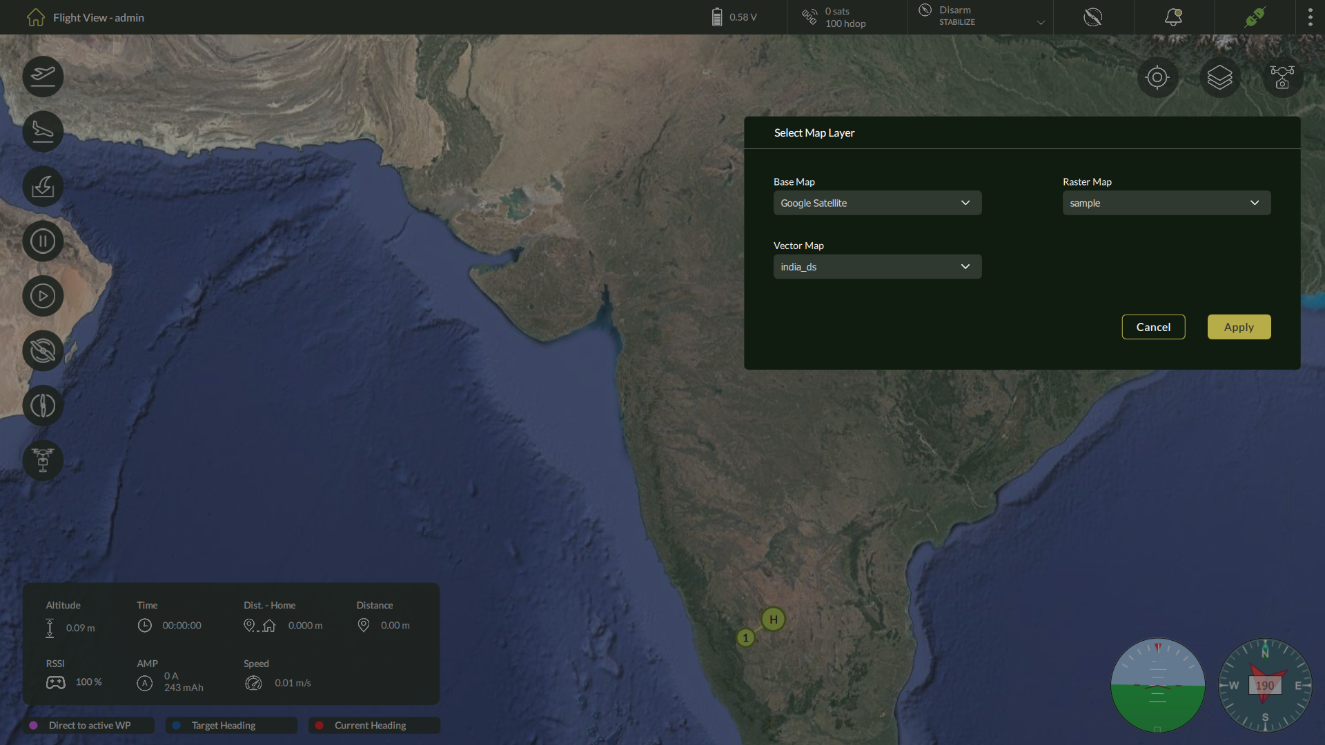
Select Map Layer Dialog
| Field | Description |
| Base Map | Select the online map source such as Google Satellite, Google Terrain, etc. |
| Raster Map | Choose from available offline raster tile sets (e.g., orthophotos or surveys). |
| Vector Map | Select the vector data layer for navigation elements, boundaries, or overlays. |
Once selections are made, click the Apply button to immediately update the displayed map on the Fly View screen.
Clicking Cancel will close the dialog without applying changes.
Use Case Benefits
- Mission Adaptability: Quickly switch map layers based on field visibility, terrain type, or mission objective.
- Offline Support: If a raster map is downloaded, it can be selected even when internet is unavailable.
- Visual Clarity: Combine vector overlays with base imagery for enhanced planning and execution.
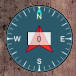
3.5 Compass and Attitude Indicator
3.5.1 Compass Indicator
| Element | Description |
| Heading Degree | Displays the drone’s current heading (e.g., 152°). |
| Orientation Ring | Indicates North, South, East, and West directions around the current heading. |
| Dynamic Update | Rotates in real time as the drone’s orientation changes. |
3.5.2 Attitude Indicator
| Feature | Description |
| Pitch Indicator | Shows the drone’s nose-up or nose-down tilt. |
| Roll Indicator | Displays lateral tilt (left/right) of the drone’s body. |
| Live Visualization | Real-time dynamic adjustment of the graphical interface based on drone motion. |
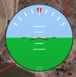
| Note: The Compass and Attitude indicators remain active during flight and are updated continuously based on telemetry received from the onboard flight controller. |